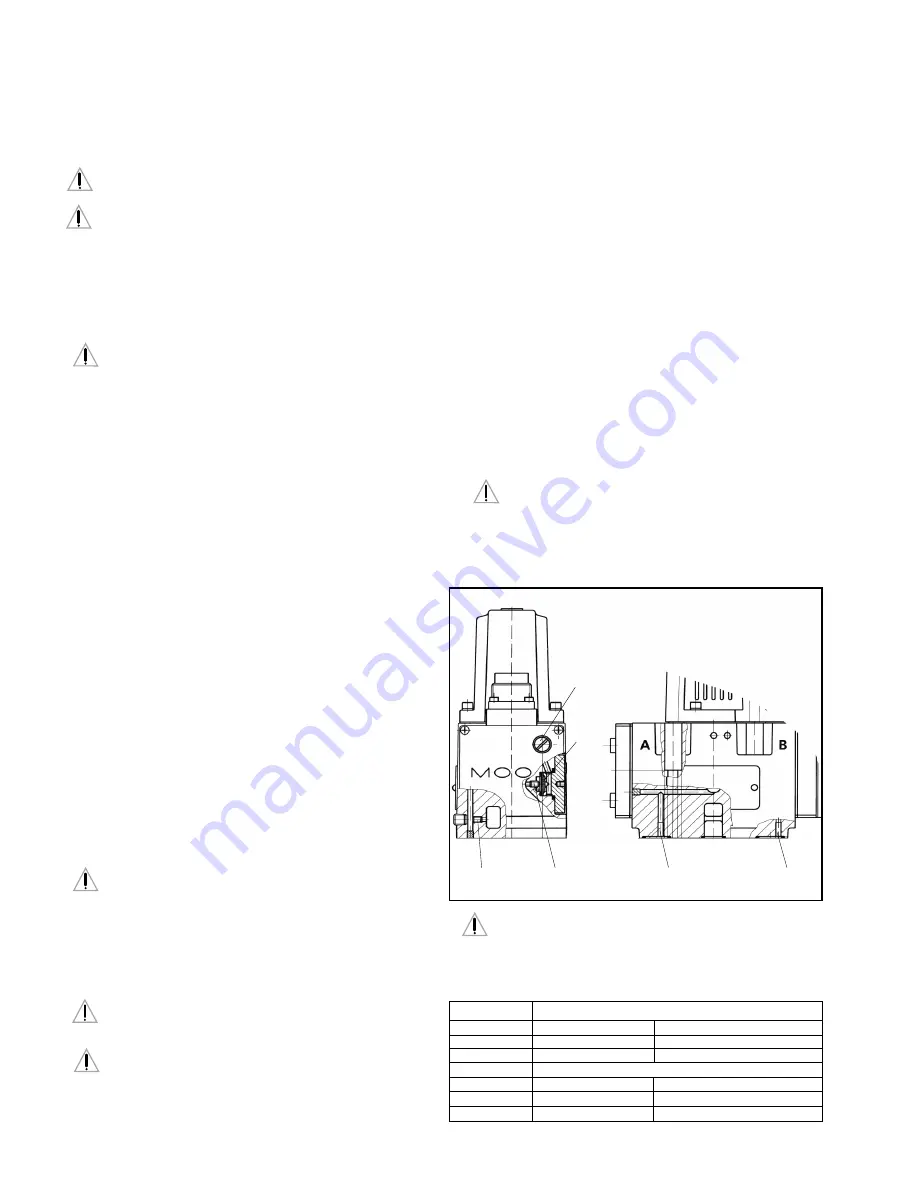
Internal/External Pilot Connection
a.
Conversion for operation with internal or external pilot connection.
The pilot connection mode as shipped is indicated by the respective
code letter of the type designation on the nameplate.
With the 5-way version, where the T and T
2
ports are interchanged
with the P port, pilot supply port X and return port Y must be
connected externally.
4
3. SAFETY INSTRUCTIONS
Warnings and Symbols
a.
Refers to special orders and prohibitions to prevent damage
b.
Refers to special orders and prohibitions to prevent injury or
extensive damage
Correct Application
a.
The D661 Series Valves are control valves suited for electrohydraulic
position, velocity, pressure and force control.
b.
The valves are designed for flow control in hydraulic systems that
operate with mineral oil based fluids. Others upon request.
c.
Using the valves for purposes other than those mentioned above is
considered contrary to the intended use. The user bears entirely the
risk of such misuse.
d.
Correct application involves also observing the operating instruction and
complying with the inspection and maintenance directives.
Organizational Measures
a.
We recommend including this operating instruction into the
maintenance plan of the machine/plant.
b.
In addition to the operating instruction, observe also all other generally
applicable legal and other mandatory regulations relevant to accident
prevention and environmental protection. Instruct the operator
accordingly.
c.
All safety and danger prevention instructions of the machine/plant must
meet the requirements of EN 982.
Selection and Qualification of Personnel
a.
Only well-trained and instructed personnel are allowed to work with Moog
control valves.
b.
Work with electrohydraulic valves must be carried out only by personnel
having special knowledge and experience in plants running with
electrohydraulic controls.
Safety Instructions for Specific Operational Phases
a.
Take the necessary precautions to ensure that the machine/plant is
used only when in a safe and reliable state.
b.
Check the machine/plant at least once per working shift for obvious
damage and defects (i.e. leakage). Report any changes to the responsible
group/person immediately. If necessary, stop the machine immediately
and secure it.
c.
In the event of malfunctions, stop the machine/plant immediately and
secure it. Have any defects rectified immediately.
d.
If the machine/plant is completely shut down for maintenance and repair
work at the valve, it must be secured against inadvertent start up by:
➢
Locking the principal control elements and removing the key.
➢
Attaching a warning sign to the main switch.
Safety Instructions for the Operation of Hydraulic Plants
a.
Work on electrohydraulic equipment must be carried out only by personnel
having special knowledge and experience in electrohydraulic controls.
b.
Check all lines, hoses and fittings of the plant regularly for leaks and
obvious damage. Repair damage immediately.
Splashed oil may cause injury and fire.
c.
Before removing the valve, depressurize all system sections to be
opened, pressure lines and accumulators of the hydraulic system
in accordance with the specific instructions for the plant.
d.
When handling oil, grease and other chemical substances, observe safety
regulations valid for each product.
4. INSTALLATION
General Information
a.
Compare model number and valve type with information from the
hydraulic schematic or bill of material.
b.
The valve can be mounted in any direction, fixed or moving.
c.
Check mounting surface flatness (0.02 mm for 100 mm) and
surface finish (Ra <1
µ
m)
d.
Pay attention to cleanliness of mounting surface and surroundings when
installing the valve.
e.
Use lint-free tissue to clean!
f.
Before installation, remove shipping plate from the valve and save it
for later use.
g.
Pay attention to correct position of ports and location of o-rings during
installation.
h.
Use M6 x 60 socket head bolts according to DIN 912 for mounting,
strength class 10.9 or 12.9, and cross torque to 13 Nm (tolerance
±
10 %)
ATTENTION
DANGER
DANGER
DANGER
DANGER
DANGER
ATTENTION
Electric
Null adjust
(behind screw plug)
Set screw
4
M4 x 6
Set screw
1
M4 x 6
Set screw
2
M4 x 6
Set screw
3
M4 x 6
X
1
)
P
Y
Filter
Servovalve D661 G
without mechanical feedback
and Proportional Valve D661 P...A/B
Pilot Flow
Set Screw M4 x 6
Supply
bore 1
bore 2
Internal P
closed
open
External X
open
closed
Pilot Flow
Set Screw M4 x 6
Return
bore 3
bore 4
Internal T
closed
open
External Y
open
closed
b.
Conversion instruction for Servovalves D661-G and Proportional
valves D661-P...A/B
1
) Check for sufficient length (100 mm) of mounting surface!
ATTENTION


