background image

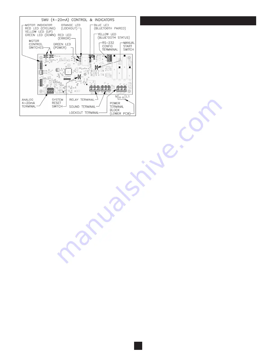
Figure 10

7

SMU Analog(4-20mA) Model

(See Figure 10)

1) Auto Timer - 

If desired, the SMU can be configured to self 

    start at regular time intervals. The auto timer function must be

    turned on, and the interval value configured. Then, the 

    SMU will start a sounding after the passing of the time interval

    selected. If auto timer is not desired, then select the auto 

    timer to be off, and apply a signal to the SOUND terminal to 

    initiate the measurement process.

2) Values - 

The 4~20mA Analog SMU needs to have the 4mA 

    & 20mA values defined. Configure the distance value down 

    from the SMU flange that you want to correspond to 4mA & 

    20mA values. This can be done either way, with 4mA when 

    vessel is empty and 20mA when vessel is full, or visa versa.

    The active signal will over range as much as 3mA and 

    21.5mA. See Page 8 for the configuration process.

3) Error Reaction -

The 4~20mA analog SMU can be config-

    ured to produce an "error" signal on the 4~20mA 

    signal. Upon an operational error, the SMU will produce a 

    current value of <2mA or >23mA. The receiving device must

    be configured with a respective threshold to recognize the 

    signal is outside of the standard operational range 

    (3~21.5mA), and that some form of error has occurred.

4) Signal -

The current signal can be adjusted to update the 

    signal in two different modes:


CONTINUOUS - 

Upon the start of a sounding, the 4~20mA 

    current value will snap to the value that corresponds to a 

    vessel full, and then will progress as the bob travels through

    its range of motion. 


EOT -

Upon the start of a sounding, the 4~20mA current 

    value will hold a value that corresponds to the previous 

    distance measurement. When the bob has reached its End 

    Of Travel, the current output will snap to a value that corre-

    sponds to the new reading.

SETUP - CONTINUED

Содержание Silo Patrol SE 344A

Страница 1: ...label on the SMU cover Verify the voltage output type cable type cable length flange style and location approval ordinary or haz ardous All SMUs are shipped with a standard plumb bob to ease instal lation If an alternate plumb bob is ordered it will be packed separately See Mechanical Installation section for method to change plumb bob In the event that information contained herein does not comple...

Страница 2: ...res the amount of cable dispensed via its unique optical sensing system The SMU s optic system is completely sealed from the internal environment of the electronics compartment which is isolated and sealed from material ingress in the mechanical compartment to ensure long term reliable operation The descent of the bob is maintained at an optimal speed by the smart motor control system which contri...

Страница 3: ...ECT ELECTR ELECTRI ELECTRIC ELECTRICA ELECTRICAL ELECTRICAL ELECTRICAL I ELECTRICAL IN ELECTRICAL INS ELECTRICAL INST ELECTRICAL INSTA ELECTRICAL INSTAL ELECTRICAL INSTALL ELECTRICAL INSTALLA ELECTRICAL INSTALLAT ELECTRICAL INSTALLATI ELECTRICAL INSTALLATIO ELECTRICAL INSTALLATION FACT ELECTRICAL INSTALLATION F ELECTRICAL INSTALLATION FA ELECTRICAL INSTALLATION FAC ELECTRICAL INSTALLATION FACTO EL...

Страница 4: ...G DIAGRAM SMU RS 485 MODELS ADV WIRING DIAGRAM SMU RS 485 MODELS ADV M WIRING DIAGRAM SMU RS 485 MODELS ADV M0 WIRING DIAGRAM SMU RS 485 MODELS ADV M00 WIRING DIAGRAM SMU RS 485 MODELS ADV M006 WIRING DIAGRAM SMU RS 485 MODELS ADV M0068 7 WIRING DIAGRAM SMU RS 485 MODELS ADV M0068 7 WIRING DIAGRAM SMU RS 485 MODELS ADV M0068 7 WIRING DIAGRAM SMU RS 485 MODELS ADV M0068 7 2 WIRING DIAGRAM SMU RS 48...

Страница 5: ...OU LOCKOUT LOCKOUT N L N N L1 N L1 POWER N L1 P N L1 PO N L1 POW N L1 POWE N L1 POWER DEPL N L1 POWER N L1 POWER D N L1 POWER DE N L1 POWER DEP N L1 POWER DEPLU N L1 POWER DEPLUGGABL N L1 POWER DEPLUG N L1 POWER DEPLUGG N L1 POWER DEPLUGGA N L1 POWER DEPLUGGAB N L1 POWER DEPLUGGABLE N L1 POWER DEPLUGGABLE N L1 POWER DEPLUGGABLE FROM BOT N L1 POWER DEPLUGGABLE F N L1 POWER DEPLUGGABLE FR N L1 POWER...

Страница 6: ... 485 network SMU Tx orange When illuminated indicates that the SMU is transmitting data out onto the RS 485 network Status yellow When flashing indicates the general well being of the on board Bluetooth radio When flashing rapidly indicates that the Bluetooth radio is currently being pro grammed and is not available for Bluetooth connections nor is the SMU able to take a sounding Off indicates the...

Страница 7: ...and 21 5mA See Page 8 for the configuration process 3 Error Reaction The 4 20mA analog SMU can be config ured to produce an error signal on the 4 20mA signal Upon an operational error the SMU will produce a current value of 2mA or 23mA The receiving device must be configured with a respective threshold to recognize the signal is outside of the standard operational range 3 21 5mA and that some form...

Страница 8: ... phone or tablet from Monitor s website at http www monitortech com apps or scan the following QR Code 1 l Install the app from an e mail Consult factory l If device does not have Wi Fi connection or mobile data service other options like transfering the app from a PC to the device via a USB connection might be available Consult factory App must be connected with the SMU through Bluetooth in order...

Страница 9: ... dependent on the protocol selected default address 1 RELAY SETTINGS RELAY ACTION FORCE RELAY RELAY THRESHOLD OFF CYCLE OPERATE ERROR LOW THRESHOLD HIGH THRESHOLD NOT ACT on ACT off No relay action energized whenever power is applied Relay relaxed while SMU is sounding ener gized when bob idle default CYCLE OPERATE Relay relaxed when error is detected energized when error dismissed When distance t...

Страница 10: ... READ ONLY Defines physical length of cable Sets max value for relay threshold cycle limit Sounding stops upon measure reaching value Also presets the time values in Descend Assist of Zone 1 Range 1Ft 150Ft typc 1Ft 200Ft special cases SMU will periodically report distance measured thus far while still sounding EXISTING MEASUREMENT This option is only viewable when Descend Assist is ON 0 008 168H ...

Страница 11: ...Factory Consult Factory Consult Factory Consult Factory Consult Factory Consult Factory Consult Factory Consult Factory Consult Factory Consult Factory Consult Factory Consult Factory SHOW REG MAP For Modbus protocols only Displays the Modbus register map as can be see in Installation Bulletin 344N 11 Menu Selection for ConfigureSensor App RS 485 Continued Factory Defaults are Shown in Bold Denote...

Страница 12: ...es relay energized Use distance from latest measure only update on good cycles relaxed if Genesis When distance thres relay energized When distance thres relay relaxed Use distance from latest measure only update on good cycles relaxed if Genesis Relay temporarily not activated on regardless of status Relay temporarily activated off regardless of status Distance threshold range 0 150ft 0 45 7m def...

Страница 13: ...tion is only viewable when Descend Assist is ON CABLE LENGTH CSL READ ONLY Defines physical length of cable Sets max value for relay threshold cycle limit Sounding stops upon measure reaching value Also presets the time values in Descend Assist of Zone 1 Range 1Ft 150Ft typc 1Ft 200Ft special cases 0 008 168H ...

Страница 14: ... errors were detected they will be indicated on the HMI2 The following error conditions are analyzed and dis played if applicable Com Error Communication between HMI2 and SMU is faulty Return Error The measurement of descent was greater than the ascent If 4 100mm 1 upward travel Index Error The measurement of ascent was greater than the descent If 4 100mm Motion Error The plumb bob did not move up...

Страница 15: ...on cable around rollers measuring wheel and through the wiper seal compartment and mounting flange Do not install wiper seals yet 7 Reattach plumb bob Pass cable through two compression sleeves around thimble and back through compression sleeves Crimp compression sleeves 8 Install wiper seals Install wiper seals as explained in the Wiper Seal Replacement section 9 Re establish operation Remove all...

Страница 16: ... The plumb bob did not travel as far when ascending as it did when descending Determine if plumb bob is trapped in material Request another measurement A subsequent motion error confirms an entrapment A subsequent index error indicates that plumb bob has freed itself Request another measurement and errors will likely cease 2 Index Error The plumb bob did not travel as far when descending as it did...

Страница 17: ... IN BRACKETS Silo Monitoring Unit SMU Digestible Plumb Bob 6 2190 Standard K Flange 6 3105 5 K Flange 6 3125 10 K Flange 6 3128 Standard Aluminum Plumb Bob 6 3103 Standard Aluminum Teflon Coated Plumb Bob 6 3123 Standard Stainless Steel Plumb Bob 6 3136 Inverted Cone Plumb Bob 6 4106 Inverted Cone Teflon Coated Plumb Bob 6 4126 Ball Float Plumb Bob 6 4108 Ball Float Teflon Coated Plumb Bob 6 4128 ...

Страница 18: ...manual to highlight important safety issues Please pay particular attention to these items Electrical Shock Caution SMUs are powered with HIGH VOLTAGE No operator serviceable parts are inside All servicing is to be performed by qualified personnel Each SMU is pro vided with a protective conductor terminal which shall be terminated to earth ground potential See Electrical Installation This product ...

Отзывы: