MFH5398_REV00.doc
Page 6 of 7
Last printed 10/23/2006
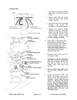
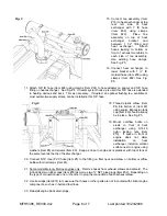
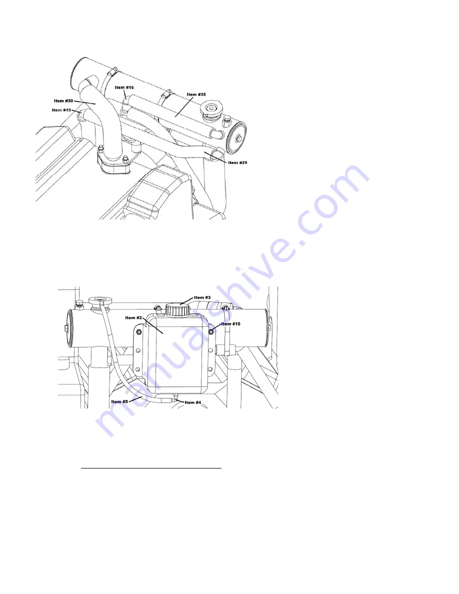
15. Connect tee assembly (Item
#16) to heat exchanger at top
rear left side of heat
exchanger with 1” ID hose
(Item #38) using clamps
(Item #23). Place Tee
assembly on top of heat
exchanger
bracket
and
between 1 1/2” fitting and
heat exchanger. Attach
hoses leading to bottom or
front of exhaust manifolds to
each side of tee assembly.
Use existing hose clamps.
See Fig. #5.
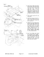
16. Connect heat exchanger to
lower bracket with 1 ½” ID
molded hose (Item #30) using
clamps (Item #22). See Fig.
#5.
17. Attach 5/8” ID hose (Item #28) using clamps (Item #24) to hose adapter on spacer and 5/8” hose
fitting on heat exchanger. See Fig. #4. If heater system hook-up is used this 5/8” hose is extended
to heating devices and back. Trim as necessary. If desired, an optional flushing tee, available at
most automotive supply stores, can be installed in this 5/8” hose.
18. Thread plastic elbow (Item
#4) into bottom of (Item #2)
using sealer. Expansion tank
cap (Item #3) should already
be in place. See Fig. #5.
19. Mount overflow bottle on
studs on front of heat
exchanger using 5/16-18
nylon locking nuts (Item
#10). If space in front of
engine does not allow
installation
on
heat
exchanger, install on vertical
surface next to engine using
washers (Item #8) and screws (Item #9). Keep as close to engine as is practical, with top of tank at
the same level as the top of heat exchanger.
20. Connect 5/16” clear PVC hose (Item #5) to the fitting on filler neck and elbow on bottom overflow
bottle with mini clamps (Item #6).
21. Some model Mercury Marine engines only: Remove hoses from exhaust elbows and discard. The
kit includes two rubber caps (Item #33) as well as two ¾” NPT pipe plugs (Item #32). Depending on
the type of connection use one or the other to plug the connection of each exhaust elbow.
22. Use tie wraps (Item #31) to make sure that hoses or other parts are not in contact with critical engine
components, such as V-belt and fuel lines.
23. Reinstall engine block drain plugs.
Fig. 5
Fig. 6


