10
VIO
GRY
BLU
GRN
YEL
ORG
RED
BRN
BLK
Common
+24Vdc
Push Bar Switch
WHT
Red Lamp
Green Lamp
Yellow Lamp
Buzzer
3 kOhm Sense
Lock Power In
Terminal
block at door
(Not supplied)
RED/BLK
RED/YEL
RED/GRN
ALPHA 1181/15C cable
(20 ft. supplied)
Push Bar
Switch (N/C)
Direct to magnet
N/C
Common
Magnetic Bond
Status Output
Relay
N/O
2
1
3
4
5
6
8
7
9
10
PAIR
11
12
13
14
PAIR
PAIR
PAIR
PAIR
PAIR
15
16
Cab
le
to
Co
n
trol
M
o
d
u
le
BLK
WHT
RED
BLK
YEL
BLK
BLU
GRN
BLK
BLK
BRN
BLK
Not used
CC-8946
5.2 Electrical Installation
All external connections to the CC-8946 are made through the attached 15-conductor cable. The
supplied cable is 20 ft. long and may be cut as necessary. A terminal block within or near the
door frame is normally used to interconnect the CC-8946 with the cable that connects with the
associated Door Control Module in the SIC.
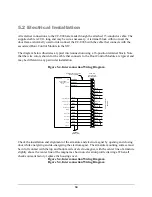
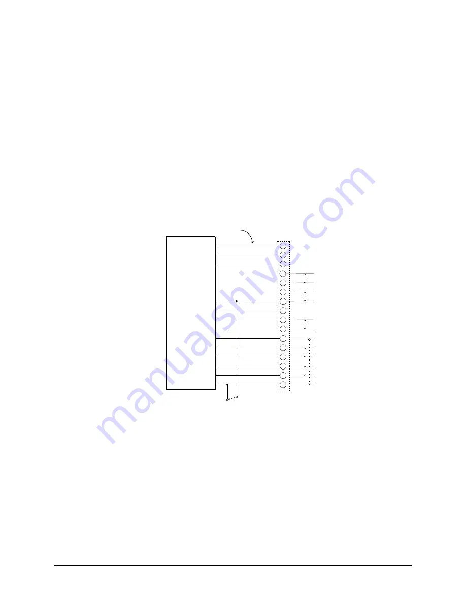
The diagram below illustrates a typical interconnection using a 16-position terminal block. Note
that the wire colors shown for the cable that connects to the Door Control Module are typical and
may be different in any particular installation.
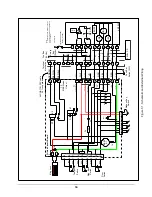
Figure 5-4, Interconnection Wiring Diagram
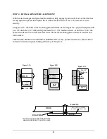
Check the installation and alignment of the armature and electro-magnet by opening and closing
door while energizing and de-energizing the electromagnet. The armature mounting surface must
be in full contact with the top and bottom rails of electro-magnet, with the center line of armature
slightly above the center line of the magnet as shown on elevation profile drawings. When all
checks out satisfactory, replace the housing cover.
Figure 5-4, Interconnection Wiring Diagram
Figure 5-4, Interconnection Wiring Diagram


