


Molnar Hoists
All Rounder
Servicing
22
Hydraulic Cylinder Replacement
Hydraulic Cylinder Replacement
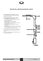
1
Isolate power to the hoist and apply lock out switch.
ie: turn power off.
A licensed electrician must perform all electrical work
2
Disconnect the wiring in the bottom junction box and
pull the mains electrical cable out through the top junction
box. Apply insulation covers to the exposed wires
3
Open the top junction box and retrieve excess coiled
electrical wire (ready to be pulled out the top).
4
Remove the oil tank
(as per Hydraulic System, page 10)
5
Remove the lift arms from the control-post carriage:
remove the split pin from the pivot pin (in the Arm Lock)
then remove the pivot pin. Remove the lift arm, and place
to side.
6
Remove the over-head limit switch trigger wires:
remove the conduit from the limit switch, and pull the
wires coiled in the top junction box from the conduit.
Disconnect the wires at the bullet points.
Remove dust cap. Feed the conduit (with electrical wires
still inside) into hole in control-post end cap to secure.
7
Disconnect the
long Wire Rope
(see
Wire Rope & Pulley
Removal: point 8,
page 14)
and reach
inside the cut-out
in the side of the
control-post to pull
the long Wire Rope
over the top brace
and out. It may need
to be fed through top
pulley position.
8
Feed the Wire Rope
back into the control-
post so the Wire Rope
is secure as you lay
the post down.
9
Remove top brace:
remove the
6 x
M10 bolts per side
securing the brace
to the post caps.
Remove the brace
and place to one side.
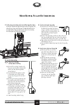
10
Lift control post:
Place a sling around the post above the
twin pulley, ensuring the sling is above
the centre of gravity. Use a lifting device
(such as crane) to secure the post as it
is loosened – use an air impact gun
to remove the 7 M16 bolts that
secure the post to the base.
Take up the tension (on the
sling), then carefully lift
post and slowly lower
face down.
Use a pallet jack to raise the top end of the post, to
remove the control-post cap. Conduit will feed out
through the top of the cap. Place cap to one side.
Lower the end of the post onto blocks.
Remove the pallet jack.
11
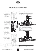
Pull the long Wire Rope out from the top of the post.
Disconnect the twin Wire Rope bracket
(as per Wire Rope
& Pulley Removal: point 2 & 3, page 14)
and remove the
twin pulley and disconnect the Wire Rope
(as per Wire
Rope & Pulley Removal: point 4, 5 & 6, page 16)
.
Place pulley to one side.
Lay the twin Wire Ropes down inside the post.
12
Remove the oil pipe retaining clip, located inside the post
(roughly in line with the top of the hydraulic cylinder),
held in position with a philips-head screw located under
the control button box.
retaining clip
oil
pipe


