background image

AT-1992 Hand Crimp Tool 

Doc No:ATS-640070100 

Release Date: 10-03-02 

UNCONTROLLED COPY


Page 1 of 15 

Revision: J 

Revision Date: 08-08-13 

Air Powered 

Crimp Tool Head 

Krimptite

 and 

VersaKrimp


Application Tooling 

Specification Sheet


Order No. 64007-0100 

Engineering No. AT 1992


FEATURES 


Quick-change tool head for the 19279-0001 (AT-200) 


Tooling kit is interchangeable with other kits in the 64001 and 64003 Series 


A precision user-friendly terminal locator wire stop holds terminals in the proper crimping position for each of the 
three nests 


3-nested tool eliminates the need for additional tools 


Pneumatic powered crimp tools help reduce fatigue and discomfort from repetitive manual crimping 


SCOPE 

Products: Krimptite

 / VersaKrimp

 Terminals and Splices 10–22 AWG and 6.0mm² - 0.5mm².  This tool head is 

intended for use in the 19279-0001 (AT-200) either hand held or with optional bench adapter 19078-0307 (ATBA) 
and foot switch. 
 

Testing 

The tensile test, or pull test, is a means of evaluating the mechanical properties of the crimped connections. The 
following chart shows the various specifications for different wire sizes and types.  The 

tensile

 strength is shown 

in 

lbs (newtons)

 and indicates the minimum acceptable force to break or separate the terminal from the 

conductor. 
 

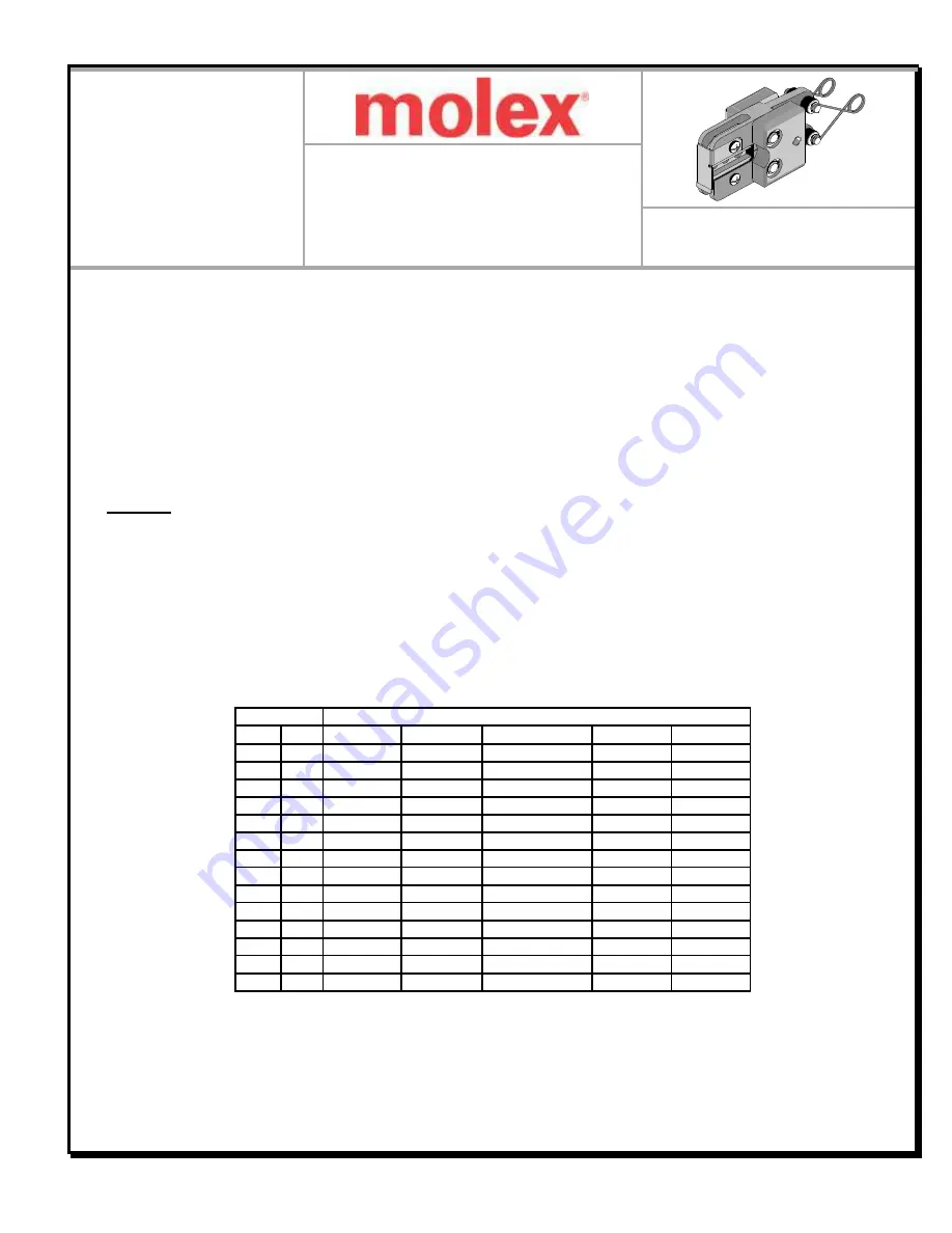
Wire Size 

Minimum Tensile Strength 

(lbs. (newtons))


AWG 

mm² 

*UL - 486 A 

*UL – 486 C 

**Military Class 2 

EN 60352-2 

EN 61238-1 

22 


8 (36) 

8 (36) 

15 (67) 


0,5 


14 (60) 

11 (50) 

20 


13 (58) 

10 (45) 

19 (85) 


0,75 


19 (85) 

17 (74) 

18 


20 (89) 

10 (45) 

38 (169) 


1,0 


24 (108) 

22 (99) 

16 


30 (134) 

15 (67) 

50 (223) 


1,5 


34 (150) 

33 (149) 

14 


50 (223) 

25 (111) 

70 (312) 


2,5 


52 (230) 

56 (248) 

12 


70 (312) 

35 (156) 

110 (490) 


4,0 


70 (310) 

89 (397) 

10 


80 (356) 

40 (178) 

150 (668) 


6,0 


81 (360) 

100 (446) 

*UL - 486 A - Terminals (Copper conductors) 

*UL - 486 C - Butt Splices, Parallel Splices 

**Military Class 2– Military Approved Terminals 

EN 60352 -2  – Telecom and signal cables 

EN 61238 -1  – Power Cables 

Содержание 64007-0100

Страница 1: ...79 0001 AT 200 either hand held or with optional bench adapter 19078 0307 ATBA and foot switch Testing The tensile test or pull test is a means of evaluating the mechanical properties of the crimped connections The following chart shows the various specifications for different wire sizes and types The tensile strength is shown in lbs newtons and indicates the minimum acceptable force to break or s...

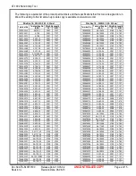
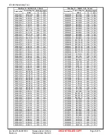
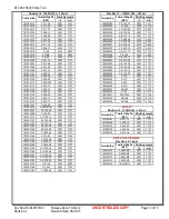
Страница 2: ... 0033 AA 121 06 0 188 4 763 19069 0035 AA 121 08 0 188 4 763 19069 0037 AA 121 10 0 188 4 763 19069 0040 AA 122 10 0 188 4 763 19069 0042 AA 122 14 0 188 4 763 19069 0043 AA 122 14R90 0 188 4 763 19069 0045 AA 122 56 0 188 4 763 19069 0047 AA 126 10 0 188 4 763 Wire Size 18 22 AWG 0 80 0 35 mm Terminal No Terminal Eng No REF Wire Strip Length In mm 19069 0048 AA 126 14 0 188 4 763 19069 0049 AA 12...

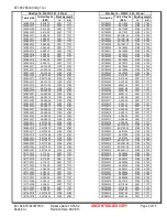
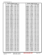
Страница 3: ...117 0029 A 196 04 0 281 7 137 19117 0030 A 196 06 0 281 7 137 19117 0031 A 196 08 0 281 7 137 19118 0018 AA 1108 02 0 188 4 763 19118 0019 AA 1108 04 0 188 4 763 Wire Size 18 22 AWG 0 80 0 35 mm Terminal No Terminal Eng No REF Wire Strip Length In mm 19118 0020 AA 115 04 0 188 4 763 19118 0021 AA 115 06 0 188 4 763 19118 0023 AA 115 08 0 188 4 763 19118 0025 AA 115 10 0 188 4 763 19118 0026 AA 146...

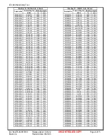
Страница 4: ... 763 19146 0004 A 338 04 0 281 7 137 19146 0005 A 338 06 0 281 7 137 19146 0007 A 391 06 0 281 7 137 19146 0008 A 391 08 0 281 7 137 19146 0009 A 391 10 0 281 7 137 Wire Size 18 22 AWG 0 80 0 35 mm Terminal No Terminal Eng No REF Wire Strip Length In mm 19146 0010 A 394 06 0 281 7 137 19146 0011 A 394 08 0 281 7 137 19146 0012 A 394 10 0 281 7 137 19146 0013 A 397 04 0 281 7 137 19146 0014 A 397 0...

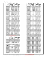
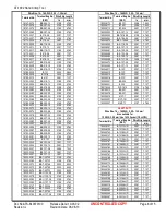
Страница 5: ...031 B 137 08 0 281 7 137 19044 0032 B 137 10 0 281 7 137 19044 0033 B 139 04 0 281 7 137 19044 0035 B 139 06 0 281 7 137 Wire Size 14 16 AWG 2 00 1 30 mm Terminal No Terminal Eng No REF Wire Strip Length In mm 19044 0037 B 139 08 0 281 7 137 19044 0039 B 139 10 0 281 7 137 19044 0137 B 101 12HD 0 281 7 137 19044 0139 B 101 14HD 0 281 7 137 19044 0140 B 101 38HD 0 281 7 137 19044 0141 B 101 56HD 0 ...

Страница 6: ...B 385 10 0 281 7 137 19088 0040 B 388 04 0 281 7 137 19088 0041 B 388 06 0 281 7 137 19088 0042 B 388 08 0 281 7 137 19088 0043 B 388 10 0 281 7 137 Wire Size 14 16 AWG 2 00 1 30 mm Terminal No Terminal Eng No REF Wire Strip Length In mm 19093 0039 BB 313 04 0 188 4 763 19093 0041 BB 313 06 0 188 4 763 19093 0043 BB 313 08 0 188 4 763 19093 0045 BB 382 06 0 188 4 763 19093 0047 BB 382 08 0 188 4 7...

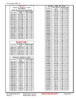
Страница 7: ...63 19129 0024 BB 1781 06 0 188 4 763 19129 0026 BB 1781 04 0 188 4 763 19129 0030 BB 1471 06 0 188 4 763 19129 0032 BB 1471 04 0 188 4 763 19140 0085 B 107 04 0 281 7 137 Wire Size 14 16 AWG 2 00 1 30 mm Terminal No Terminal Eng No REF Wire Strip Length In mm 19140 0085 BB 107 04 0 188 4 763 19140 0086 B 107 06 0 281 7 137 19140 0086 BB 107 06 0 188 4 763 19140 0087 B 124 04 0 281 7 137 19140 0088...

Страница 8: ...BB U 137 08 0 188 4 763 19203 0085 BB U 137 10 0 188 4 763 19203 0147 BB T 323 06 0 188 4 763 19203 0148 BB T 325 14 0 188 4 763 19203 0149 BB T 337 06 0 188 4 763 19203 0150 BB U 137 06 0 188 4 763 Wire Size 14 16 AWG 2 00 1 30 mm Terminal No Terminal Eng No REF Wire Strip Length In mm 19203 0170 B S 131 0 296 7 540 19203 0171 B T 331 0 296 7 540 19203 0172 B T 304 0 281 7 137 19203 0202 B S 127 ...

Страница 9: ...C 136 06 0 281 7 137 19069 0233 C 136 08 0 281 7 137 19069 0234 C 136 08R90 0 281 7 137 19069 0236 C 140 10 0 281 7 137 Wire Size 10 12 AWG 5 00 3 00 mm Terminal No Terminal Eng No REF Wire Strip Length In mm 19069 0238 C 140 14 0 281 7 137 19069 0241 C 140 38 0 281 7 137 19069 0244 C 140 56 0 281 7 137 19079 0011 C 1006 MS 0 281 7 137 19087 0145 C 1103 08 0 281 7 137 19087 0147 C 1106 06 0 281 7 ...

Страница 10: ...7 137 19203 0159 C U 128 06 0 281 7 137 19203 0160 C U 128 08 0 281 7 137 19203 0161 C U 130 14 0 281 7 137 19203 0162 C U 130 56 0 281 7 137 19203 0163 C U 140 38 0 281 7 137 19203 0167 C S 146 0 234 5 950 19203 0169 C T 303 0 281 7 140 19203 0182 C T 328 08 0 281 7 144 Wire Size 10 12 AWG 5 00 3 00 mm Terminal No Terminal Eng No REF Wire Strip Length In mm 19203 0182 C T 330 14 0 281 7 137 19203...

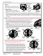
Страница 11: ...e locator blade or wire stop and remove the crimped terminal Inspect for proper crimp location Locator is adjustable up and down to keep terminals straight after crimping 5 When crimping butt splices the locator must be removed Insert the wire into the butt splice Position the splice and the wire in proper coded nest with conductor crimp on the conductor barrel of the splice The splice should be a...

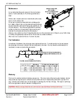
Страница 12: ...l at the oil points shown in Figure 6 every 5 000 crimps or monthly will significantly enhance the tool life and ensure a stable calibration When tool is not in use store the tool in a clean dry area Tool Calibration A Certificate of Calibration See last page was supplied with the tool To recalibrate this tool measurements should be taken from each conductor nest and compared to this chart The too...

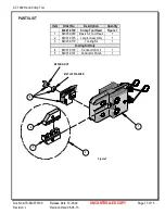
Страница 13: ...on Date 08 08 13 PARTS LIST Item Order No Description Quantity 64007 0100 Crimp Tool Head Figure 7 1 64005 0000 Basic Air Tool Head 1 2 64007 0375 Locator Assembly 1 3 64003 0170 Tooling Kit 1 Tooling Kit Only 4 64001 0102 Conductor Anvil 1 5 64001 0101 Conductor Punch 1 Figure 7 1 2 M4 WING NUT M4 FLAT WASHER 4 5 3 ...

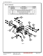
Страница 14: ... List Continued Item Order No Description Quantity 64005 0000 Basic Air Tool Head Figure 8 1 64005 0103 Nose Guard 1 2 64000 0077 Repair Kit Springs Rods Pivots Rings and Washers 1 3 N A M4 by 12 Long Freedrive Pan Head Screw 1 4 N A M4 by 30 Long Freedrive Pan Head Screw 1 5 N A 3 16 by 3 8 Long Dowel Pin 1 Available from an Industrial supply company such as MSC 1 800 645 7270 ...

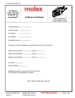
Страница 15: ...g No AT 1992 Tool Order Number Tool Eng Number Tool Revision Serial Number Date of Manufacture Pin Gauge of Conductor Nest Nests or Slug height if the nest is the F Crimp style Range Conductor Nest 1 Actual Range Conductor Nest 2 Actual Range Conductor Nest 3 Actual Technician Date of Calibration Calibration should be done every 5 000 cycles or 3 months Tools should be lubricated during this opera...

Отзывы: