Hand Crimp Tool for Poseidon II Crimp Terminals
Doc No: ATS-6382782HM
Release Date: 03-04-16
UNCONTROLLED COPY
Page 3 of 6
Revision: A
Revision Date: 03-04-16
PIVOT
LOCATOR
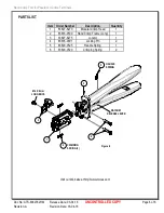
Figure 4
REMOVE
CRIMPED WIRE
OPEN WIRE
STOP
6.
Push the wire until it stops. See Figure 3.
Note:
Do not push the wire too far. This will result in the
locator being rotated out of position and the crimp will be
damaged.
7.
Close the tool until the ratchet releases, the tool handles will
then spring open.
8.
Before removing the crimped wire, pivot the terminal locator
out. See Figure 4.
9.
While holding the locator out lift up on the wire stop at the
same time, carefully remove the crimped terminal.
Note:
The tamper proof ratchet action will not release the tool
until it has been fully closed.
Maintenance
It is recommended that each operator of the tool be made aware of, and responsible for, the following
maintenance steps:
1.
Remove dust, moisture, and other contaminants with a clean brush, or soft, lint free cloth.
2.
Do not use any abrasive materials that could damage the tool.
3.
Make certain all pins; pivot points and bearing surfaces are protected with a thin coat of high quality machine
oil. Do not oil excessively. The tool was engineered for durability but like any other equipment it needs
cleaning and lubrication for a maximum service life of trouble free crimping. Light oil (such as 30 weight
automotive oil) used at the oil points, every 5,000 crimps or 3 months, will significantly enhance the tool life.
4.
Wipe excess oil from hand tool, particularly from crimping area. Oil transferred from the crimping area onto
certain terminations may affect the electrical characteristics of an application.
5.
When tool is not in use, keep the handles closed to prevent objects from becoming lodged in the crimping dies,
and store the tool in a clean, dry area.
Miscrimps or Jams
Should this tool ever become stuck or jammed in a partially closed position,
Do Not
force the handles
open or
closed
. The tool will open easily by lifting the ratchet release lever. See Figure 8.
WIRE
CONDUCTOR
PUNCH
TERMINAL
WIRE STOP
BLADE
Figure 2
LOCATOR
CONDUCTOR
ANVIL
TERMINAL
WIRE
CONDUCTOR
PUNCH
WIRE AGAINST
WIRE STOP
Figure 3
INSULATION
PUNCH
INSULATION
ANVIL


