Hand Crimp Tool for Poseidon II Crimp Terminals
Doc No: ATS-6382782HM
Release Date: 03-04-16
UNCONTROLLED COPY
Page 2 of 6
Revision: A
Revision Date: 03-04-16
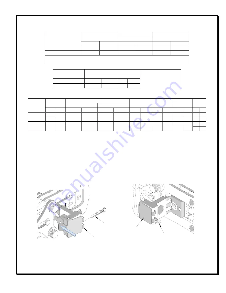
CRIMP SPECIFICATIONS
Terminal Series No.
Bell mouth
Cut-off Tab Maximum
Conductor Brush
(Contact side)
mm
In.
mm
In.
mm
In.
173041
0.10-0.60
.004-.024
0.13
.005
0.25-0.50
.010-.020
173042
0.10-0.60
.004-.024
0.13
.005
0.25-0.65
.010-.030
To achieve the conductor brush specification, special care must be taken, or a light touch
must be maintained while presenting wire against the wire stop.
Terminal Series No.
Bend up Bend down Twist Roll
Seam
Seam shall not be open and
no wire allowed out of
the crimping area
Degree (Max)
Degree (Max)
173041
3
3
5
10
173042
3
3
5
10
After crimping, the conductor profile should measure the following.
Terminal
Series No
Wire Size
Conductor Crimp
Insulation Crimp
Pull Force
Minimum
Profile
Height
Width
Height (Max.) Width (Max.)
AWG mm
2
mm
In.
Mm
In.
mm
In.
mm
In.
N
Lb. 16 18
173041
16
--- 1.15-1.25 .045-.049 1.90-2.00 .075-.079 2.30
.090 2.50 .098 133.5 30.0 X
18
--- 1.00-1.10 .039-.043 1.90-2.00 .075-.079 2.30
.090 2.50 .098 89.0 20.0
X
173042
16
--- 1.15-1.25 .045-.049 1.90-2.00 .075-.079 2.30
.090 2.50 .098 133.5 30.0 X
18
--- 1.00-1.10 .039-.043 1.90-2.00 .075-.079 2.30
.090 2.50 .098 89.0 20.0
X
OPERATION
Open the tool by squeezing the handles together, at the end of the closing stroke, the ratchet mechanism will
release the handles, and the hand tool will spring open.
1.
Select the desired terminal listed in the preceding chart.
2.
Swing the terminal locator away from the crimp tool.
3.
Press down on the wire stop on the locator. Insert the terminal into the nest opening as shown in Figure 1.
4.
Return the locator to its original position.
5.
While holding the locator against the hand tool insert the proper wire size into the terminal. See Figure 2.
TERMINAL
Figure 1
PUSH HERE
TO OPEN
WIRE STOP
SWING LOCATOR
OPEN
TERMINAL SEATED
IN LOCATOR
CLOSE WIRE
STOP


