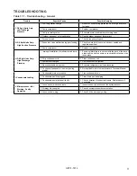
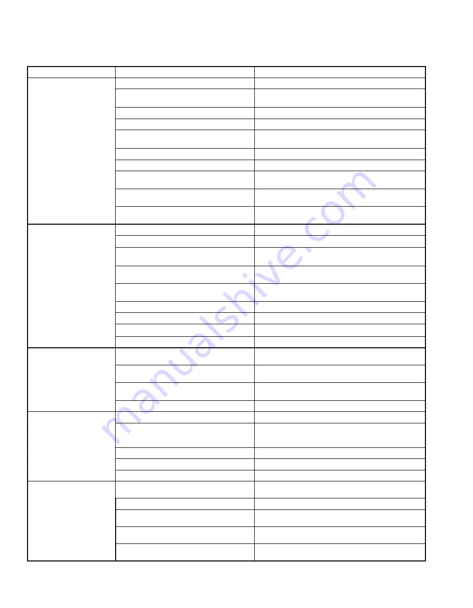
Modine Manufacturing Varsity ZCF 1000 Скачать руководство пользователя страница 16

16

AIR14-501.2

TROUBLESHOOTING

Table 16.1 - Troubleshooting - General

Trouble

Possible Cause

Possible Remedy

A. Unit Not Operating - 

     Power On

1. Unit mounted disconnect in the “OFF” position. 1. Turn the disconnect switch to the “ON” position.
2.  Unit mounted 3-speed selector switch in the 

“0” position.

2. Turn the 3-speed selector switch to the “1, 2, or 3” position.

3. Unit switched OFF in the microprocessor.

3. Consult microprocessor documentation.

4. Delay on start set incorrectly.

4. Consult microprocessor documentation.

5. Unit not in occupied mode.

5.  Consult microprocessor documentation, and consult 

microprocessor occupied setpoints.

6. Fire/smoke alarm tripped.

6. De-energize and re-energize unit.

7. Tripped circuit breakers.

7. Reset the tripped circuit breaker(s).

8. Loose mains or control wiring.

8.  With power OFF from distribution panel inspect the field 

wiring connections in the electrical panel. 

9. Occupancy sensor malfunction.

9.  Inspect connections beginning with sensor input from the 

microprocessor.

10.  Hot water freeze protection (optional) stat 

tripped.

10. Manually reset at stat.

B.  Unit Operating -  

No Mechanical 

Heating / Cooling

1. Heating/cooling not required.

1. Verify applicable set point with return air temperature.

2. No output from microprocessor.

2. Consult microprocessor documentation.

3.  DX Split Units Only: HP/LP pressure safety 

switch(es) tripped (open).

3.  Inspect high and low system pressures and wiring.  

Check for dirty filters in Heat Pump mode. 

4.  DX Split Units Only: Internal overload switch 

on compressor tripped (open).

4.  Wait for compressor motor windings to cool down  

(This switch is automatic reset).

5. Loose control wiring connections.

5.  Inspect connections beginning with compressor output 

from the microprocessor.

6. Tripped circuit breakers.

6. Reset the tripped circuit breaker(s).

7. Low temperature unit lockout.

7. Consult microprocessor setpoints. 

8. DX Split Units Only: Compressor faulty.

8. Replace compressor.

9. Condensate pan/pump float switch tripped.

9. Check condensate pan/pump and piping for blockage.

C. No Indoor Fan

1. Motor tripped on internal overload.

1.  Let motor cool down and reset - possible bad motor or 

blocked filter.

2. Fan not required

2.  Consult microprocessor documentation, or set thermostat 

to “ON”. Check if unit is in unoccupied and standby mode.

3. No power to the fan.

3.  Check to make sure plugs are locked in place and all pins 

are secure. Check for 24V control signal.

4. Current sensor fault.

4. Make sure sensor is functioning correctly.

D. Hot Water / Chilled 

     Water Valve Not 

     Operational (Option)

1. Heating not required.

1. Consult microprocessor documentation.

2. Loose wiring connections.

2.   Inspect connections beginning with valve output from the 

microprocessor. Check to ensure 24V supply power is 

present at actuator.

3. Faulty heating actuator.

3. Replace actuator if faulty.

4. Isolation valves are open.

4. Check for additional external isolation valves.

5. Check for DC control signal.

5. Check for 2-10vDC signal from microprocessor.

E.  DX Split Units Only: 

Low Suction Pressure 

(LP Switch Tripped)

1. Low refrigeration charge.

1.  Measure unit operating pressures. Add charge and check 

for leaks.

2. Clogged filter(s).

2. Replace filter(s) as necessary.

3. Clogged liquid line filter drier.

3.  Replace drier with a direct replacement. Follow proper 

procedure.

4.  Improper expansion valve setting or valve 

malfunctioning.

4. Check operation and superheat settings.

5. Low/restricted supply airflow.

5.  Check diffusers, filters and supply motor to ensure 

appropriate airflow.

Содержание Varsity ZCF 1000

Страница 1: ...nded for a qualified installation and service agency A qualified installation and service agency must perform all installation and service of these appliances 2 ZCV and ZCF units with DX evaporator coils contain the refrigerant R 410A Review the R 410A Material Safety Data Sheet MSDS for hazards and first aid measures 3 Refrigerant charging should only be carried out by an EPA certified air condit...

Страница 2: ...n 3 Handling 3 Preparation 3 Drainage 3 Electrical 3 Installation 3 Piping Installation 4 Piping Insulation 5 Wiring 5 Terminal Strip Connections 5 Start Up Procedure 6 Pre Start Checks 6 Unit Start Up Procedure 6 Typical Sequence of Operation 7 8 Start Up Sheet Example 9 10 Dimensions 11 12 Technical Data 13 Component Layout 14 Maintenance 15 Troubleshooting 16 17 Replacement Parts Model Nomencla...

Страница 3: ...ould be sealed with waterproof sealant Drainage Units with cooling coils have a condensate drain pan connection and 3 4 ID condensate line The condensate drain pan connection is field changeable and can be mounted on either the left or right side of the unit To change the connection location remove the condensate line from the elbow Remove the elbow from the drain pan and remove the plug from the ...

Страница 4: ...1 Condensing unit is typically factory charged for a 15 foot lineset For additional lineset lengths please refer to manufacturer s charging chart See the installation and maintenance manual provided with the condensing unit for installation evacuation and system charge information 1 Chilled water and hot water coils are supplied from the factory with unions Field installed piping can be mounted to...

Страница 5: ...xtra cable must be left outside the panel to allow the panel to open fully Failure to follow these instructions may cause damage to the wiring and or the unit Terminal Strip Connections The terminal strip connections are designed to clamp down on the wires To properly connect the wires to the terminal strip 1 Push a small flat head screwdriver into the square hole on the terminal Press firmly unti...

Страница 6: ...p information 1 DX Cooling models only Ensure that the condensing unit start up procedure has been carried out as detailed in the condensing unit installation and maintenance manual 2 DX Cooling models only The compressor should be isolated by removing the connection at the Y1 terminal on the indoor unit Main power can now be applied to the indoor and outdoor units A system electrical check can no...

Страница 7: ...ide air temperature is below 55 F Hot Water or Steam with Valve Control Units with a hot water or steam coil and non Carel controls desiring valve control shall use a spring return normally open modulating valve operated by a proportional signal 2 10VDC or a tri state 24VAC signal Units with Carel controls desiring valve control shall use a modulating control valve with a proportional signal When ...

Страница 8: ... a call for heating The valve shall always open when the outside air temperature drops below 40 F This is to prevent the coil from freezing or nuisance tripping of the freeze stat The 2 position hot water valve shall be closed when the 2 position chilled water valve is open if equipped The valve is controlled by a 24VAC digital output The 2 position valve used on a 2 pipe changeover system shall o...

Страница 9: ...9 AIR14 501 2 START UP SHEET EXAMPLE Figure 9 1 Start Up Sheet EXAMPLE Page 1 ...

Страница 10: ...10 AIR14 501 2 START UP SHEET EXAMPLE Figure 10 1 Start Up Sheet EXAMPLE Page 2 ...

Страница 11: ...11 AIR14 501 2 DIMENSIONS Figure 11 1 Front Discharge Unit Table 11 1 Unit Dimensions Model Size Dimensions inches W1 W2 750 62 36 1000 74 48 1250 86 60 1500 98 72 ...

Страница 12: ...12 AIR14 501 2 DIMENSIONS Figure 12 1 Down Discharge Unit Table 12 1 Unit Dimensions Model Size Dimensions inches W1 W2 750 62 36 1000 74 48 1250 86 60 1500 98 72 ...

Страница 13: ...6 0 88 3 Row gal 0 72 0 91 1 1 1 28 4 Row gal 0 92 1 17 1 42 1 66 CONNECTIONS Water Coils Inches Unions with 3 4 female solder joint Evaporator Coil Inches 3 4 OD Suction 1 2 OD Liquid Steam Coil Inches 1 NPT Condensate Line Inches 3 4 ID condensate line UNIT WEIGHT approximate Shipping Weight lbs 375 420 470 520 Operating Weight lbs 320 365 410 450 FILTER 1 Woven Fiberglass 70 75 Arrestance Quant...

Страница 14: ...1 2 COMPONENT LAYOUT Figure 14 1 Exploded View PIPING TOP ACCESS PANELS BASE ASSEMBLY DAMPER ASSEMBLY CONTROL PANEL FILTER COIL ASSEMBLY BLOWER ASSEMBLY END PANELS BOTTOM ACCESS PANELS DISCHARGE AIR PANEL ASSEMBLY ...

Страница 15: ...cessary Remove the filter support bracket and slide the filter s out of the track Replace with new filter s and reinstall the filter support bracket see Figure 14 1 Never run the unit without filters Every SIX 6 MONTHS Before the heating and cooling season 1 Check for correct fan operation no excessive noise or vibrations With the Disconnect Switch in the OFF position 2 Inspect all electrical circ...

Страница 16: ...ections 5 Inspect connections beginning with compressor output from the microprocessor 6 Tripped circuit breakers 6 Reset the tripped circuit breaker s 7 Low temperature unit lockout 7 Consult microprocessor setpoints 8 DX Split Units Only Compressor faulty 8 Replace compressor 9 Condensate pan pump float switch tripped 9 Check condensate pan pump and piping for blockage C No Indoor Fan 1 Motor tr...

Страница 17: ...er installation of wall sleeve and louver 1 Ensure splitter plate is in contact with the back of the louver blade and the unit to ensure no re circulation of exhaust air takes place 2 Dirty condenser coils 2 Clean condenser coil 3 System overcharged 3 Remove excess refrigerant 4 Noncondensables in system 4 Evacuate refrigerant circuit and recharge 5 Condenser fan speed is too slow cooling mode 5 N...

Страница 18: ...m Outside Air R Bottom Return Air No Outside Air S Top Return Air No Outside Air 9 Discharge Air DA E Front Discharge with Duct Collar F Front Disch with Dbl Defl Grille G Down Disch with Dbl Defl Grille 10 Cooling Option CO 0 None 2 2 Row Chilled Water Hot Water 2 Pipe 3 3 Row Chilled Water Hot Water 2 Pipe 4 4 Row Chilled Water Hot Water 2 Pipe 5 Direct Expansion DX Cooling Only 11 Heating Optio...

Страница 19: ...19 AIR14 501 2 SERIAL PLATE Figure 19 1 Serial Plate EXAMPLE ...

Страница 20: ...UIPMENT MANUFACTURED BY BUYER BUYER S REMEDY FOR BREACH AS LIMITED HEREIN SHALL BE LIMITED TO ONE YEAR FROM DATE OF SHIPMENT FROM SELLER FOR GAS FIRED PRODUCTS INSTALLED IN HIGH HUMIDITY APPLICATIONS AND UTILIZING STAINLESS STEEL HEAT EXCHANGERS BUYER S REMEDY FOR BREACH AS LIMITED HEREIN SHALL BE LIMITED TO TEN YEARS FROM DATE OF SHIPMENT FROM SELLER These warranties are issued only to the origin...

Отзывы: