MobileAccess EnCOVER VE Скачать руководство пользователя страница 14

Overview 

Dual Band EnCOVER VE™ Instant Coverage Solution User Manual 

6


1.2.1.2 

VCU Rear Panel 

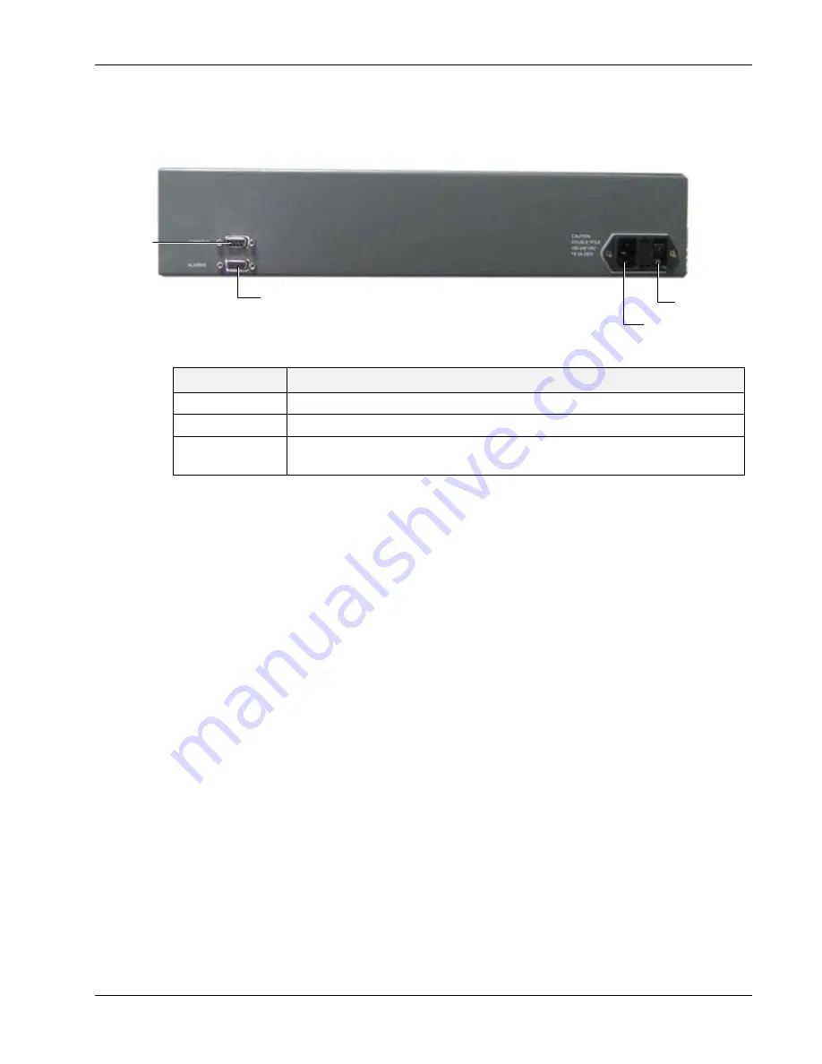
The rear panel includes the power input, the AUX alarms and service personnel connections. 


Figure 5. VCU Rear Panel 

Table 3: VCU Rear Panel Description 

Connector 

Description 

Console 

RS232 local connection for service personnel 

Alarms 

AUX alarms connections  - see 


4.2 

Power Input 

Standard 3-pins AC power connector equipped with an ON/OFF switch. 

90-264V AC, 47-63 Hz AC; 350W power consumption maximum. 


PWR On/Off 
switch 

AC connector

AUX Alarms 

Console

connector

Содержание EnCOVER VE

Страница 1: ...EnCOVER VE Dual Band Instant Coverage Solution User Manual REV A00 Date DEC 2009...

Страница 2: ...l Band EnCOVER VE Instant Coverage Solution User Manual II MobileAccess 8391 Old Courthouse Road Suite 300 Vienna VA 22182 Tel 1 866 436 9266 1 703 848 0200 TAC 1 800 787 1266 Fax 1 703 848 0280 http...

Страница 3: ...arrantee and Repair MobileAccess tests and inspects all its products to verify their quality and reliability MobileAccess uses every reasonable precaution to ensure that each unit meets their declared...

Страница 4: ...OF MERCHANTABILITY AND FITNESS FOR A PARTICULAR PURPOSE MOBILEACCESS SHALL NOT BE LIABLE FOR ANY OTHER DAMAGE INCLUDING BUT NOT LIMITED TO INDIRECT SPECIAL OR CONSEQUENTIAL DAMAGES ARISING OUT OF OR...

Страница 5: ...2 EN 301489 1 V1 5 1 2004 EN 61000 V4 6 2005 EN 55022 V4 2 2001 FCC Part 15 VCCI Class A for VCU and Class B for VAP Radio GSM DCS EN 301502 V8 1 2 2001 EN 301908 v3 2 1 2006 EN 300 609 4 V8 02 2000 C...

Страница 6: ...e EnCOVER VE system List of Acronyms Abbreviation Description DB Dual Band PoE Power Over Ethernet PSE Power Sourcing Equipment SME Small Medium Enterprise STP Shielded Twisted Pair UTP Unshielded Twi...

Страница 7: ...ions 10 3 2 Infrastructure Requirements 11 3 3 Coverage and Installation Planning 12 3 3 1 Types of Environments 12 3 3 1 1 Open environment 13 3 3 1 2 Standard Environment 13 3 3 1 3 Dense Environmen...

Страница 8: ...2 Verifying Coverage 36 5 3 Naming the VAPs Verifying Connections and Monitoring 36 6 Navigating the Management Application 39 6 1 Opening a Session and Authentication Levels 39 6 2 Main Window 40 6 3...

Страница 9: ...Ethernet jacks already installed at the enterprise site They are powered via PoE technology and managed via an EnCOVER VE Control Unit VCU located in the floor s communication shaft For site coverage...

Страница 10: ...the main communication IDF closet interfaces to the service provider s RF equipment and provides secure central management to up to twelve VCUs and all connected VAPs Slave VE Control Unit Slave VCU i...

Страница 11: ...ribute the wireless services via integrated internal antennas or external antennas optional VAP models and provide Ethernet connectivity to the LAN terminals 1 2 System Elements This chapter describes...

Страница 12: ...1 VCU Ports Description Ports Description Service1 Service2 RF connections two wireless services to the service provider RF equipment e g picocells Coax cables EGSM UMTS Service 1 UMTS Service 2 EGSM...

Страница 13: ...olid Orange associated unit is faulty or connected unit is not managed due to mismatch type VoIP phone VCU connected to a slave VCU etc Fast Blinking Green User invoked identify command on the corresp...

Страница 14: ...nections Figure 5 VCU Rear Panel Table 3 VCU Rear Panel Description Connector Description Console RS232 local connection for service personnel Alarms AUX alarms connections see 4 2 Power Input Standar...

Страница 15: ...port relevant when connected to jacks that provide an Ethernet connection to a user terminal The VAP can be mounted hung on the wall or placed on a flat surface such as a desk The following figure sh...

Страница 16: ...ed antenna option For example if the VAP includes an external antenna connector the signal is only transmitted via the external antenna connector 1 3 2 System Monitoring and Management The EnCOVER VE...

Страница 17: ...Installation Workflow Dual Band EnCOVER VE Instant Coverage Solution User Manual 9 2 Installation Workflow The following figure summarizes the main steps of the installation procedure...

Страница 18: ...VCUs Slave VCUs installed at the IDF telco cabinet of each covered floor and connected to the cabling patch panel Wireless service signal from Master VCU to VCUs routed through dedicated Ethernet CAT...

Страница 19: ...P cable from Master VCU to Slave VCUs with run lengths NOT exceeding 100m 300ft CAT 5e 6 UTP or STP cable from VCU to each VAP with run lengths NOT exceeding 100m 300ft VAPs can be connected over exis...

Страница 20: ...he wireless services This section provides information on coverage criteria in various types of environments Open Standard Dense and Merged and provides rules of thumb for various installations of the...

Страница 21: ...et 42 m Recommended maximum distance of VAPs from outer walls 90 feet 27 m 83 feet 25 m 67 feet 21 m Coverage Area per VAP 25 425 sqft 2 362 sqm 21 375 sqft 1 986 sqm 14 250 sqft 1 324 sqm 3 3 1 2 Sta...

Страница 22: ...f areas closer to the denser area For example in a cubical area with the outside wall having offices simply locate the VAPs a little closer to the outside offices to provide coverage through the offic...

Страница 23: ...ch VAP in the facility VAPs may be added or removed at anytime for optimal coverage 3 For each jack to be used for connecting a VAP check if the jack is already connected to the Ethernet switch via th...

Страница 24: ...ld reduce coverage in that area by the other VAPs VAP 5 is an example of a unit that provides good coverage down the hallways VAPs 11 and 13 are placed closer to the offices to cover them well but on...

Страница 25: ...Dual Band EnCOVER VE Instant Coverage Solution User Manual 17 The following figure depicts an actual measured quantified coverage of a floor area planed according to the above rules Figure 11 Distrib...

Страница 26: ...d configuration procedures of the EnCOVER VE Control Unit VCU in each floor These should be performed only after planning the floor coverage and installation locations as described in the previous sec...

Страница 27: ...panel that feeds the dedicated CAT 6 or 7 cabling system 3 Connect or request the service provider s service personnel to connect the provider s signal source Macro cell Micro cell Pico cell or BDA to...

Страница 28: ...Alarm Pin Number Auxiliary Alarm 1 26 8 8 9 4 2 3 7 10 11 3 4 5 6 12 13 2 6 7 5 14 15 1 4 2 2 Alarm Output Connections The controller can provide Major and Minor output alarms These alarms can be conn...

Страница 29: ...h panel using dedicated CAT6 cables 4 According to VAPs layout plan as explained in section 3 4 2 connect the Ethernet switch cables see section 4 3 1 for more detailed explanation If the jack to be u...

Страница 30: ...ve VCUs and note that the VCU PWR LED is lit and that the VAP Status LEDs complete initialization and show a solid light 4 3 1 Connections of VAP Ethernet Cables For VAPs installed on currently ACTIVE...

Страница 31: ...n using a cross cable After performing the initial configuration and assigning the Master VCU an IP the system can be connected monitored and configured via a remote management connection 2 The config...

Страница 32: ...nternet Protocol TCP IP Properties dialog appears NOTE The Master VCU is supplied with the default IP address 192 168 1 1 In order to communicate with the unit it is necessary to assign your computer...

Страница 33: ...ster VCU Unit 1 Perform a local connection to the Master VCU unit by connecting the Master VCU front panel Management port and a laptop computer 2 Open a web browser and type the Master VCU IP address...

Страница 34: ...Solution User Manual 26 The EnCOVER VE Web GUI appears 4 On the invoked application window choose the Management tab in the main menu bar and click the IP Settings tab on the side bar Network Topolog...

Страница 35: ...figuration the Master VCU can be accessed remotely via Ethernet Set the following available parameters DHCP Dynamic Host Configuration Protocol N A IP address Static IP address Default definitions The...

Страница 36: ...U appears in the Network Topology Tree as Master VCU Select the Master VCU by clicking on it 9 Before configuring the Master VCU it is recommended to give the unit an indicative name To assign the Mas...

Страница 37: ...or each connected service up to two Each service Service1 Service2 is configured through its corresponding tab To configure the service RF parameters Select the Service tab Service1 Service2 of the se...

Страница 38: ...0 33dBm Define UL attenuation level for each service 0 25dB Notes 1 Max expected Pin and Service CF parameters are service dependent and can be obtained from your service provider 2 The remaining para...

Страница 39: ...d Service 1 Service Off User has disabled service Service 2 DL RF Pwr Low RED DL RF Power is lower than 5dBm Service 2 DL RF Pwr High RED the input power exceeds the maximum limit and cannot be attenu...

Страница 40: ...VCUs management and configuration is performed through a remote connection to the Master VCU via the web management Before provisioning the Slave VCUs verify that the Master VCU unit to which it is co...

Страница 41: ...has a default name of the form VCUPx name where Px Master VCU port number to which the Slave VCU is connected Name user defined name 2 To assign the Slave VCU an indicative name Select the Module Inf...

Страница 42: ...ck in the appropriate location to provide optimal coverage see sections 3 4 and 5 1 2 5 1 1 VAP Kit Contents The EnCOVER VE Dual Band Solution VAP kit includes Note VAPs are provided with two mounting...

Страница 43: ...3 1 Aesthetics of the VAP location 5 1 2 1 Desk mount Secure the Desk mount adaptor to the EnCOVER VE Access Pod using the supplied screws Connect the RJ 45 jumper cable CAT 5e 6 to the VAP Place the...

Страница 44: ...eb GUI internal antenna is enabled by default Note The maximum external antenna gain should not exceed 10 dBi Verify that the VAP receives power and sync up to the VCU via the LEDs on the unit 5 2 Ver...

Страница 45: ...ned name 3 In the Network Topology Tree under the Control Unit verify that a GREEN or RED circle is displayed for each connected VAP If a VAP is not green select the VAP from the network topology tree...

Страница 46: ...6 When required to transmit the RF signal through a connected external antenna if VAP model supports this option Refer to the Service 1 and or Service 2 tabs Enable the External Antenna option Note I...

Страница 47: ...ening a Session and Authentication Levels After the initial configuration as explained in 4 4 1 the EnCOVER VE system can be accessed via the network To access the system 1 Open a web browser and type...

Страница 48: ...Monitor Provides a summarized view of the system status Config uration Provides the selected units configuration parameters and alarms Events Provides the events list and trap mask Set up Provides wiz...

Страница 49: ...Configuration window is accessed by clicking on the Config tab in the main menu bar The information and parameters displayed in the Configuration sub tabs vary depending on whether a VCU or VAP is sel...

Страница 50: ...VCU Slave VCU or VAP 6 3 2 Network Topology Tree The Configuration Network Topology Tree appears on the left hand side when the Config tab is selected and displays the Master VCU Slave VCUs and VAPs i...

Страница 51: ...r VCU Slave VCU or VAP in the network topology tree an icon representing the unit is displayed in the Configuration tab display area The following table provides a description of the LEDs displayed fo...

Страница 52: ...nfig uration tab in the menu bar located at the top of the window and click the VCU Alarms sub tab If one or more alarms occur the corresponding Status indicator is illuminated in RED If the VCU is OK...

Страница 53: ...indow and click the VAP Alarms sub tab If one or more alarms occur the corresponding Status indicator is illuminated in RED If the VAP is OK and no fault occurs the Overall Status indicator will show...

Страница 54: ...the Module Info sub tab The following information is displayed Field Description Name User defined name for system element up to 20 characters Serial Number Factory set ID number Product Revision Rev...

Страница 55: ...re displayed one for each active service The displayed RF parameters are similar for both service tabs 6 3 6 1 Master VCU Slave VCU Service RF Tab Note The RF parameters are not displayed for control...

Страница 56: ...utomatically assigned by the system according to the DL frequency Max Exp Pin Maximum expected input power from the BTS Used for adjustment procedure Range 0 33 dBm User defined Pin Actual measured Pi...

Страница 57: ...pprox 10 dB less than the required level High measured power is over the maximum required level UL Pout Level Corresponds to defined DL Pout level Antenna Select External only if an external antenna i...

Страница 58: ...ts physical location as explained in section 5 3 If a name was not configured or for some other reason a specific VAP cannot be physically located physically identify the VAP by following the instruct...

Страница 59: ...cess Pod will start blinking fast You will need to physically locate the VAP to see the blinking LED 4 Locate the Access Pod 5 Once found it is advisable to assign it an identifiable name via the Acce...

Страница 60: ...x expected power 7 Service2Off Major user setting service to off 8 Control Unit Faulty Major HW failure in CU 9 OverTemperature Minor VCU temperature is too high 10 AbnormalSetup Minor Msmatched servi...

Отзывы: