


2
22
2-
--
-24
24
24
24
Confirming the operation
Confirming the operation
Confirming the operation
Confirming the operation
2
22
2Unpacking to Installation
Unpacking to Installation
Unpacking to Installation
Unpacking to Installation
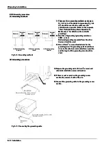
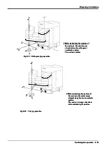
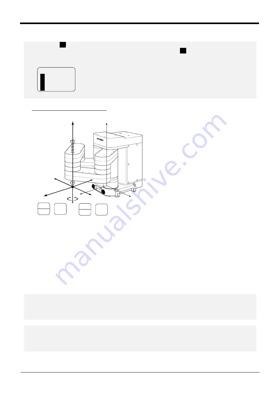
* Rotating around the Z axis
* Rotating around the Z axis
* Rotating around the Z axis
* Rotating around the Z axis
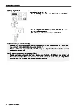
When the [MOVE] + [+C (J6)] keys are
When the [MOVE] + [+C (J6)] keys are
When the [MOVE] + [+C (J6)] keys are
When the [MOVE] + [+C (J6)] keys are
pressed, the Z axis will rotate in the plus
pressed, the Z axis will rotate in the plus
pressed, the Z axis will rotate in the plus
pressed, the Z axis will rotate in the plus
direction.
direction.
direction.
direction.
When the [MOVE] + [-C (J6)] keys are
When the [MOVE] + [-C (J6)] keys are
When the [MOVE] + [-C (J6)] keys are
When the [MOVE] + [-C (J6)] keys are
pressed, the Z axis will rotate in the minus
pressed, the Z axis will rotate in the minus
pressed, the Z axis will rotate in the minus
pressed, the Z axis will rotate in the minus
direction.
direction.
direction.
direction.
The position of the end axis will not move.
The position of the end axis will not move.
The position of the end axis will not move.
The position of the end axis will not move.
◇◆◇
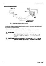
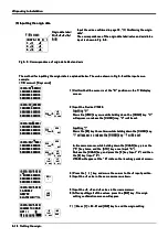
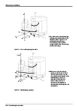
When an X appears on the T/B screen display
◇◆◇
◇◆◇
When an X appears on the T/B screen display
◇◆◇
◇◆◇
When an X appears on the T/B screen display
◇◆◇
◇◆◇
When an X appears on the T/B screen display
◇◆◇
If the robot is moved outside the movement area with any of the axes, an X will appear. In this case, move the
If the robot is moved outside the movement area with any of the axes, an X will appear. In this case, move the
If the robot is moved outside the movement area with any of the axes, an X will appear. In this case, move the
If the robot is moved outside the movement area with any of the axes, an X will appear. In this case, move the
axis in the opposite direction.
axis in the opposite direction.
axis in the opposite direction.
axis in the opposite direction.
In the example on the left, further linear movement in the same direction is not possible.
In the example on the left, further linear movement in the same direction is not possible.
In the example on the left, further linear movement in the same direction is not possible.
In the example on the left, further linear movement in the same direction is not possible.
JOINT LOW
JOINT LOW
JOINT LOW
JOINT LOW
X X +360.00
X X +360.00
X X +360.00
X X +360.00
Y +280.00
Y +280.00
Y +280.00
Y +280.00
Z +
1
70.00
Z +
1
70.00
Z +
1
70.00
Z +
1
70.00
X
X
X
X
X
X
X
X
X
X
X
X
X
X
X
X
X
X
X
X
+
X axis
+
Z axis
+
Z axis
-
-
-
-
+
+
+
+
+X
+X
+X
+X
-X
-X
-X
-X
-Y
-Y
-Y
-Y
+Y
+Y
+Y
+Y
+Z
+Z
+Z
+Z
-Z
-Z
-Z
-Z
J4
J4
J4
J4
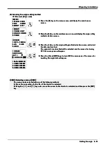
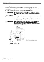
Changing the direction of the end axis
Changing the direction of the end axis
Changing the direction of the end axis
Changing the direction of the end axis
*
The Position of the
*
The Position of the
*
The Position of the
*
The Position of the
frange will not move.
frange will not move.
frange will not move.
frange will not move.
+
+
+
+
+
+
+
+
STEP
STEP
STEP
STEP
MOVE
MOVE
MOVE
MOVE
STEP
STEP
STEP
STEP
MOVE
MOVE
MOVE
MOVE
-C
-C
-C
-C
(J6)
(J6)
(J6)
(J6)
0
0
0
0
ABC
ABC
ABC
ABC
+C
+C
+C
+C
(J6)
(J6)
(J6)
(J6)
5
5
5
5
STU
STU
STU
STU
◇◆◇
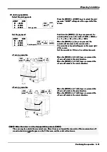
When alarm No. 5
1
50 occurs
◇◆◇
◇◆◇
When alarm No. 5
1
50 occurs
◇◆◇
◇◆◇
When alarm No. 5
1
50 occurs
◇◆◇
◇◆◇
When alarm No. 5
1
50 occurs
◇◆◇
If alarm No.
If alarm No.
If alarm No.
If alarm No.
5
1
50
5
1
50
5
1
50
5
1
50
(ORIGIN NOT SET) occurs, the origin has not been set correctly. Reconfirm the value input for
(ORIGIN NOT SET) occurs, the origin has not been set correctly. Reconfirm the value input for
(ORIGIN NOT SET) occurs, the origin has not been set correctly. Reconfirm the value input for
(ORIGIN NOT SET) occurs, the origin has not been set correctly. Reconfirm the value input for
the origin data.
the origin data.
the origin data.
the origin data.
◇◆◇
Tool length
◇◆◇
◇◆◇
Tool length
◇◆◇
◇◆◇
Tool length
◇◆◇
◇◆◇
Tool length
◇◆◇
The default tool length is 0mm, and the control point is the center of the end axis.
The default tool length is 0mm, and the control point is the center of the end axis.
The default tool length is 0mm, and the control point is the center of the end axis.
The default tool length is 0mm, and the control point is the center of the end axis.
After installing the hand, set the correct tool length in the parameters. Refer to the separate manual "Detailed
After installing the hand, set the correct tool length in the parameters. Refer to the separate manual "Detailed
After installing the hand, set the correct tool length in the parameters. Refer to the separate manual "Detailed
After installing the hand, set the correct tool length in the parameters. Refer to the separate manual "Detailed
Explanation of Functions and Operations" for details.
Explanation of Functions and Operations" for details.
Explanation of Functions and Operations" for details.
Explanation of Functions and Operations" for details.


