


25
Your company internal use only.
Copyright (C) Mitsubishi Electric Corporation.
NR-242UM-13LND0,13-WS
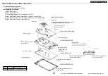
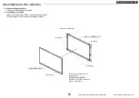
DISASSEMBLING PROCEDURES
●
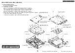
Disassembling procedures
In reverse of assembling procedures.
●
Assembling procedures
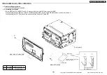
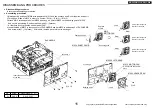
1.Attach M041 to M017.
2.Attach M018 to M017.
* Do not forget to let an FPC go through from LCD.
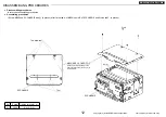
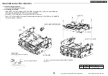
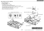
3.Attach M062 to M018 and screw with
Ⓔ
. [4 places. except
Ⓔ
(a)]
4.Connect FPC of LCD and FPC of the touch panel to connector of M062.
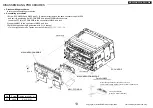
5.Attach M025 to M062 and screw with
Ⓔ
(a).
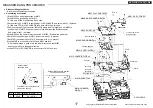
No.
Screw
Tighten torque(N
・m)
Ⓔ
M2X3
0.16
~
0.3
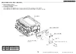
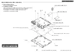
Detail of FPC
*60 pins side of the LCD part
Ⓔ
x 4
Ⓔ
Bend it near the pasting up
end face of the FPC.
Arrange it after drawing an FPC
to the outside of M062.
Positioning (2 places)
Lock a connector after
the insertion in FFC.
Remove a protection sheet of
the back side.
Remove a surface protection
sheet.
Arrange it like the
right figure.
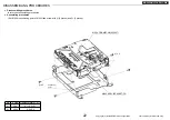
Tab joint (8 places)
There is no clip.
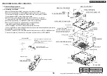
Put an FPC through the
hole of M018.
Remove the tape.
Positioning
Positioning
After having attached M025, tighten together
with M025 and M062 with this screw.
M025: SHIELD-MONI
M062: ASSY-PCB-MONI
M018: HOLDER-PCB
M041: ASSY-LCD
M017: HOLDER-LCD
Remove the tape.


