


17
Your company internal use only.
Copyright (C) Mitsubishi Electric Corporation.
NR-242UM-13LND0,13-WS
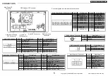
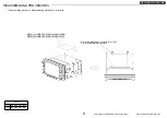
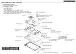
DISASSEMBLING PROCEDURES
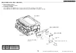
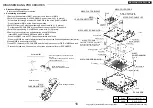
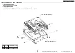
Push M007 into the inside not to
swell out on the top.
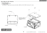
M035: SHEET-TAP
S5-CHASSIS
Positioning
Positioning
Positioning
Detail of M007
assembly work
Detail of M035 pasting position
Positioning
M015: CHASSIS-
DIGITAL
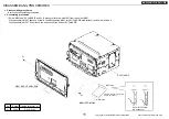
M015: CHASSIS-DIGITAL
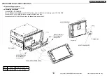
Ⓐ
x 4
Ⓐ
x 4
Ⓐ
x 4
Ⓐ
x 6
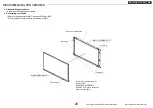
End face norm
Fit norm
Pasting position
positioning
Terminal surface
The upper part of the
terminal surface.
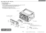
M029: SHEET-HS
M061: ASSY-PCB-SD
Electric parts A
M007: FLAT-CABLE 24P
●
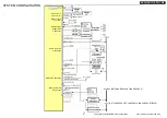
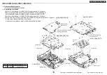
Disassembling procedures
In reverse of assembling procedures.
●
Assembling procedures
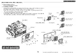
1.Stick M030 on a pasting position of M015.
2.Stick M035 on positioning K of M015.
* At this time, M035 fit positioning K and stick.
3.Set positioning F of M015 to positioning L of S5-CHASSIS, and screw with
Ⓐ
. (6 places)
* At this time, FFC(b) of S5-CHASSIS let a hole of M015 go through.
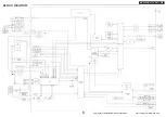
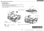
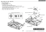
4.Remove the cap of the connector of M053(Pattern side: 2 places) and set M053 to
positioning G of M015 and push the part of silk after inserting BtoB connector.
And screw with
Ⓐ
. (4 places)
5.Stick M029 on the center of electric parts A of M053. (Slanted line part area)
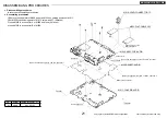
6.Set M042 to positioning H of M015, and screw with
Ⓐ
. (4 places)
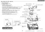
7.Set M061 to positioning J of M015, and screw with
Ⓐ
. (4 places)
8.Insert M007 in a connector of M053 and M061 and lock.
* After having locked it, push it into the lower direction so that M007
does not swell out in the upper direction.
9.Insert FFC(b) of S5-CHASSIS in a connector of M061 and lock.
Hole
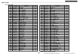
No.
Screw
Tighten torque(N
・m)
Ⓐ
2.6X6
0.4 +0.2/-0.1
M042: ASSY-COVER-DIGITAL
M053: S4-PCB-DIGITAL
M030: SHEET-DIGITAL
Positioning L


