


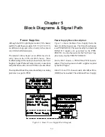


5-6
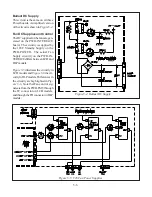
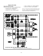
Ballast DC Supply
This circuit is the same on all three
Power boards. A simplified version
of the circuit is shown in
Figure 5-4.
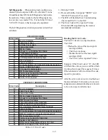
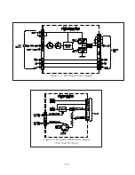
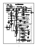
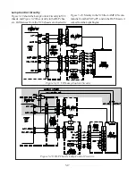
Fan DC Supplies and Control
The DC supplies for the fans are gen-
erated on the PWB-INTERFACE
board,. The circuitry is supplied by
the 18VF Standby Supply on the
PWB-POWER. The actual Fan
Supply circuitry on the PWB-IN-
TERFACE differs between LCD and
DLP models.
Figure 5-5
illustrates the circuitry in
LCD models and
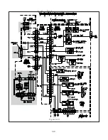
Figure 5-6
the cir-
cuitry in DLP models. Differences in
the circuitry are high lighted in
Fig-
ure 5-6.
Note that Fan control sig-
nals are from the PWB-FMT, through
the FC connector on LCD models,
and through the FB connector in DLP
models.
Figure 5-4: Ballast DC Supply
Figure 5-5: V28 Fan Power Supplies
Содержание Mr.Slim WD-52627
Страница 2: ......
Страница 4: ...II...
Страница 29: ...DM PWB DEMOD1 PWB DEMOD2 PWB E2P PWB PWB LOCATIONS POWER PWB RISERPWB MICRO PWB FMTPWB 2 5 TERMINAL PWB...
Страница 50: ...4 8...
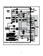
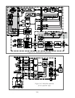
Страница 54: ...5 4 Figure 5 3A V28 PWB POWER DC to DC Supplies...
Страница 55: ...5 5 Figure 5 3B DLP PWB POWER DC to DC Supplies...
Страница 58: ...5 8 Figure 5 7 DLP Engine Power Supply Figure 5 8 Hard Disc HDD Power Supply V30 and V31 Only...
Страница 59: ...5 9 Figure 5 9...
Страница 60: ...5 10 Figure 5 10...
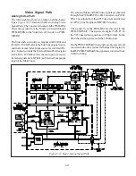
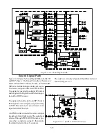
Страница 63: ...5 13 Figure 5 13 Analog Video Signal Path...
Страница 64: ...5 14 Figure 5 15 Video Record Path V30 and V31 only Figure 5 14 Analog Video Signal Path...
Страница 69: ...5 19 Figure 5 22 DLP Engine Protect Circuitry Figure 5 23 Short Detection Circuitry...
Страница 70: ...5 20...
Страница 71: ......
Страница 72: ...Copyright 2005 Mitsubishi Digital ElectronicsAmerica Inc 9351 Jeronimo Road Irvine CA 92618 1904...


