


3-4
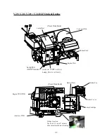
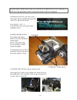
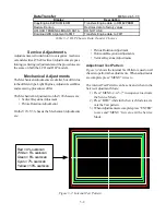
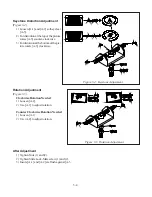
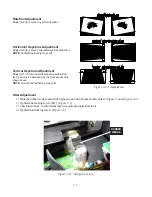
Keystone Distortion Adjustment
(Figure 3-4)
1) Loosen [A-1] and [A-2] so they clear
[A-3].
2) For distortion at the top of the picture
rotate [A-3] counter-clockwise.
3) For distortion at the bottom of the pic-
ture rotate [A-3] clockwise.
After Adjustment
1) Tighten Nuts (1) and (2).
2) Tighten Slide Lock-Mate screw (1) and (2).
3) Insure [A-1] and [A-2] are flush against [A-3
Rotation Adjustment
(Figure 3-5)
Clockwise Rotation Needed
1) Loosen [A-2].
2) Use [A-1] to adjust rotation.
Counter Clockwise Rotation Needed
1) Loosen [A-1}.
2) Use )A-2] to adjust rotation,
Figure 3-4: Keystone Adjustment
Figure 3-5: Rotation Adjustment
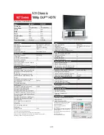
Содержание Mr.Slim WD-52627
Страница 2: ......
Страница 4: ...II...
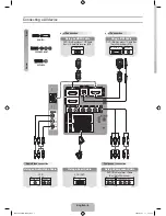
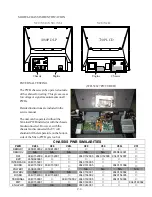
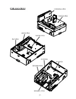
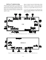
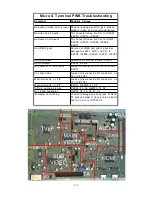
Страница 29: ...DM PWB DEMOD1 PWB DEMOD2 PWB E2P PWB PWB LOCATIONS POWER PWB RISERPWB MICRO PWB FMTPWB 2 5 TERMINAL PWB...
Страница 50: ...4 8...
Страница 54: ...5 4 Figure 5 3A V28 PWB POWER DC to DC Supplies...
Страница 55: ...5 5 Figure 5 3B DLP PWB POWER DC to DC Supplies...
Страница 58: ...5 8 Figure 5 7 DLP Engine Power Supply Figure 5 8 Hard Disc HDD Power Supply V30 and V31 Only...
Страница 59: ...5 9 Figure 5 9...
Страница 60: ...5 10 Figure 5 10...
Страница 63: ...5 13 Figure 5 13 Analog Video Signal Path...
Страница 64: ...5 14 Figure 5 15 Video Record Path V30 and V31 only Figure 5 14 Analog Video Signal Path...
Страница 69: ...5 19 Figure 5 22 DLP Engine Protect Circuitry Figure 5 23 Short Detection Circuitry...
Страница 70: ...5 20...
Страница 71: ......
Страница 72: ...Copyright 2005 Mitsubishi Digital ElectronicsAmerica Inc 9351 Jeronimo Road Irvine CA 92618 1904...