


4-3
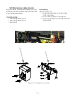
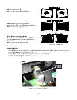
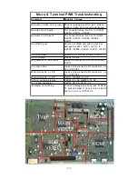
Interface Troubleshooting
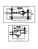
The Interface PWB provides the service technician with
a convenient test point for many of the peripheral com-
ponents such as the Engine, Lamp Circuit, Fans and
Sensors. It is easily accessible as it is located in the
center of the set, directly in the rear of both the LCD
and DLP models.
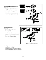
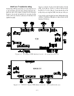
Figure 4-2
shows the layout of the Interface for the
LCD, V28 Chassis.
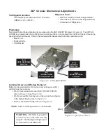
Figure 4-3
shows the layout for
the DLP, V29/30/31 chassis. These layouts are as the
technician is viewing the PWB from the rear of the set.
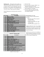
To save time, use the Symptom/Cause information along
with the Circuit Block Diagrams to make checks on the
Interface PWB first.
Figure 4-2: V28 Chassis PWB Interface Layout… As viewed from the rear.
Figure 4-3: V29/30/31 Chassis PWB Interface Layout… As viewed from the rear.
V28
V29/30/31
Содержание Mr.Slim WD-52627
Страница 2: ......
Страница 4: ...II...
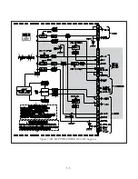
Страница 29: ...DM PWB DEMOD1 PWB DEMOD2 PWB E2P PWB PWB LOCATIONS POWER PWB RISERPWB MICRO PWB FMTPWB 2 5 TERMINAL PWB...
Страница 50: ...4 8...
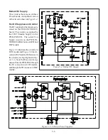
Страница 54: ...5 4 Figure 5 3A V28 PWB POWER DC to DC Supplies...
Страница 55: ...5 5 Figure 5 3B DLP PWB POWER DC to DC Supplies...
Страница 58: ...5 8 Figure 5 7 DLP Engine Power Supply Figure 5 8 Hard Disc HDD Power Supply V30 and V31 Only...
Страница 59: ...5 9 Figure 5 9...
Страница 60: ...5 10 Figure 5 10...
Страница 63: ...5 13 Figure 5 13 Analog Video Signal Path...
Страница 64: ...5 14 Figure 5 15 Video Record Path V30 and V31 only Figure 5 14 Analog Video Signal Path...
Страница 69: ...5 19 Figure 5 22 DLP Engine Protect Circuitry Figure 5 23 Short Detection Circuitry...
Страница 70: ...5 20...
Страница 71: ......
Страница 72: ...Copyright 2005 Mitsubishi Digital ElectronicsAmerica Inc 9351 Jeronimo Road Irvine CA 92618 1904...


