


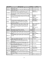


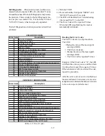

PWB NAME
PWB FUNCTION
LAYER
CIRCUIT
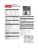
POWER1
Converts input AC current to DC supply voltages and creates
ballast board voltage.
2 layer
V28 POWER SUPPLY
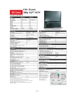
POWER2
Converts input AC current to DC supply voltages and creates
ballast board voltage.
2 layer
V29 POWER SUPPLY
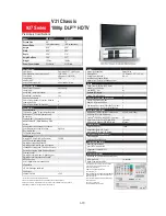
TERMINAL
Analog inputs and outputs for audio and video. Also houses
the audio select circuitry. All analog audio and video
connected to the terminal PWB are sent to the PWB-MICRO
then eventually to the DM for processing before conversion in
the PWB-FMT.
2 layer
PINJACKS
AUDIO SWITCH
MICRO
Final processing and amplifier for audio. Main and sub video
switching. TV micro processor and system 5 micro processor
well as HDMI decoding.
4 layer
TV MICRO
PIC MICRO
HDMI
AUDIO CONTROL
AUDIO AMP
VIDEO SWITCH
RISER
TVGuide data slicer and RS232 transceiver. Accepts
composite video from SUB-Y signal from video switch on
PWB-MICRO, slices the data from the carrier signal and
sends it to the PWB-DM.
4 layer
G+ (TVGuide)
M-LINK (RS232)
DM
Digital and analog video/audio signal processing. All video
signals are converted to digital YPrPb and output to PWB-
FMT. All Audio signals converted to analog left and right
signals and sent to PWB-MICRO for final processing and
amplification
6 layer
X226 (ATI Xilleon 226)
MPEG encoder
A/D converter
DPM7
POD (CableCard)
1394
TUNERS
DEMOD1
Demodulates ATSC signal from main tuner.
4 layer
T313R
DEMOD2
Demodulates sub signal. V30+ and V31 only
4 layer
T310R
FMT-V28
Converts digital YPrPb video signal, input from DM, to TMDS
(DVI) RGB video signal, output to engine. The format output
is 720p
6 layer
SUITE
FMT MICRO
TMDS Transmitter
FMT-V29
Converts digital YPrPb video signal, input from DM, to TMDS
(DVI) RGB video signal, output to engine. The format output
is 1080p
8 layer
ADC
PRELUDE
SUITE
FMT MICRO
TMDS Transmitter
FRONT
Allows for an analog input connect in the front of the TV. This
signal is passed to the Terminal PWB.
2 layer
Front Inputs
PREAMP
Receives IR signal from remote control and sends the
commands to the TV micro and to System5 micro on the
PWB-MICRO.
2 layer
Remote Control IR
SW-FILTER
Limit switch detects the presence of a filter installed. This
circuit sends a signal to the TV micro to turn off the TV if a
filter is not detected. V28/V28+ only
2 layer
Filter Detect
SW-LAMP
Limit switch detects the presence of a lamp installed. This
circuit sends a signal to the TV micro to turn off the TV if a
lamp is not detected.
2 layer
Lamp Detect
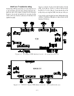
INTERFACE
Houses the lamp/engine/fan protection circuitry. Sends signal
to the FMT or the PWB-MICRO to turn TV off if there is
sensor or fan failure.
2 layer
FAN CONTROL
CONNECTORS
CONTROL
Front panel control buttons. Sends signal to TV micro on
PWB-MICRO.
2 layer
Panel Buttons
E2P
EE2PROM stores many of the data variables for adjustment
and other functions.
4 layer
ENG-PWR
Generates DC voltages to DLP engine (V29/V30/V30+/V31
only)
4 layer
V29 only : engine power
2-6
Содержание Mr.Slim WD-52627
Страница 2: ......
Страница 4: ...II...
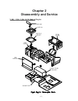
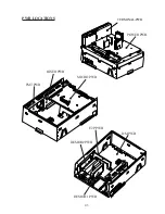
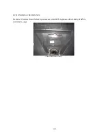
Страница 29: ...DM PWB DEMOD1 PWB DEMOD2 PWB E2P PWB PWB LOCATIONS POWER PWB RISERPWB MICRO PWB FMTPWB 2 5 TERMINAL PWB...
Страница 50: ...4 8...
Страница 54: ...5 4 Figure 5 3A V28 PWB POWER DC to DC Supplies...
Страница 55: ...5 5 Figure 5 3B DLP PWB POWER DC to DC Supplies...
Страница 58: ...5 8 Figure 5 7 DLP Engine Power Supply Figure 5 8 Hard Disc HDD Power Supply V30 and V31 Only...
Страница 59: ...5 9 Figure 5 9...
Страница 60: ...5 10 Figure 5 10...
Страница 63: ...5 13 Figure 5 13 Analog Video Signal Path...
Страница 64: ...5 14 Figure 5 15 Video Record Path V30 and V31 only Figure 5 14 Analog Video Signal Path...
Страница 69: ...5 19 Figure 5 22 DLP Engine Protect Circuitry Figure 5 23 Short Detection Circuitry...
Страница 70: ...5 20...
Страница 71: ......
Страница 72: ...Copyright 2005 Mitsubishi Digital ElectronicsAmerica Inc 9351 Jeronimo Road Irvine CA 92618 1904...


