background image

T
 2005
2006

  ECHNICAL
RAINING

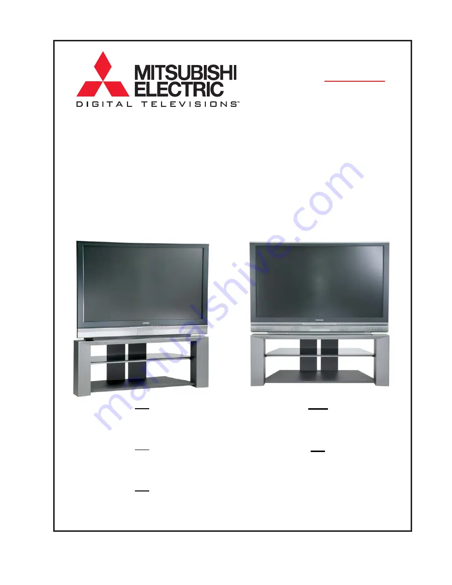
Projection Television
Training Manual
Including…

Down-to-1

High Speed Troubleshooting

COPYRIGHT © 200

6

 MITSUBISHI DIGITAL ELECTRONICS AMERICA, INC.

ALL RIGHTS RESERVED

1080p

DLP™

720p

LCD

WD-52527 WD-62527
WD-52528 WD-62528

V28

V29

WD-52627
WD-62628

WD-52628 WD-62827 WD-73727
WD-62628

WD-73827

V31

WD-62927
WD-73927

V30

WD-52526 WD-62526

V28L

Содержание Mr.Slim WD-52627

Страница 1: ...o 1 High Speed Troubleshooting COPYRIGHT 2006 MITSUBISHI DIGITAL ELECTRONICS AMERICA INC ALL RIGHTS RESERVED 1080p DLP 720p LCD WD 52527 WD 62527 WD 52528 WD 62528 V28 V29 WD 52627 WD 62628 WD 52628 W...

Страница 2: ......

Страница 3: ...ures Option Menu 3 1 Service Mode 3 1 MechanicalAdjustments 3 2 ElectricalAdjustments 3 8 Chapter 4 Down to 1 Troubleshooting Front Panel LEDs 4 1 Self Diagnostics 4 2 Interface Troubleshooting 4 3 Sy...

Страница 4: ...II...

Страница 5: ...Division MitsubishiElectric sSemiconductorDivisionmarkets advanced digital and mixed signal products that pro videunmatchedflexibility designreuse innovativepack agingoptions ultra lowpowerandprovenhi...

Страница 6: ...AirPurifiersJetTowelHand Dryers Compressors Semiconductors Optoelectronic Microwave RFSemiconductors Mitsubishi Electric US Products Services Home Theater Presentation Imaging Products HighDefinitionT...

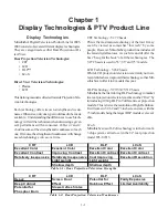
Страница 7: ...55 65 and 73 models LCD Technology V28 Chassis While LCD projection television is certainly not new recentstrideshaveimprovedthistechnologysothatMit subishicanofferitin4modelsthisyear DLPTechnology V...

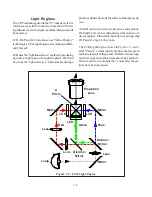
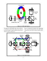
Страница 8: ...CD Light Engine pictureaslightreflectsoffthesurfaceofthedisplayde vice AnLCDmustuse3devicestoproduceacolorpicture DLP and LCoS can be configured as either single or 3 deviceengines Mitsubishicurrently...

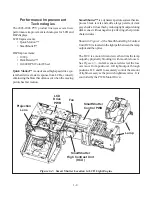
Страница 9: ...r wheel and the fieldsequential methodofdisplayingthered green andblueelementsofthepicture Figure 1 3 shows an LCoS engine in a 3 chip arrange ment Like LCD it produces each color individually Andlike...

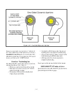
Страница 10: ...sthisbyreducinglightoutputduring dark scenes without negatively affecting other picture characteristics Shown in Figure 1 4 the SmartShutter High Contrast Unit HCU islocatedinthelightpathbetweenthelam...

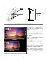
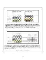
Страница 11: ...rrors Thisyieldsasmoothappearancewith out pixelgaps A comparison of a 720p DMD and a 1080p DMDisgiveninFigure1 7 A720pDMDusesasquarepixelarrangement while a 1080p DMD uses a diagonal pixel ar rangemen...

Страница 12: ...1 6 Figure 1 7 720p DMD vs 1080p DMD Pixel Arrangement Square Pixel Arrangement Diagonal Pixel Arrangement Final Pixel Image 1280X720 1920X1080 720p DMD Chip 1080p DMD Chip 720p DMD 1080p DMD...

Страница 13: ...e This process is completd every 1 60 of a second dis playing all of the data every frame just as is the case for other traditional DMDs The resulting image exhibits the same pixel resolution as the o...

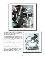
Страница 14: ...the light path between the lamp and DLP optics Figure 1 10 shows the DB module after it has been re movedfromtheengine Thelightshuttercanbeseenat the top of the picture It moves into and out of the l...

Страница 15: ...rvice Theyare PWBs are constructed with Lead Free Solder Mirror area is easier to access on 52 LCD allDLPtosimplifycleaning EliminationofribboncablesintheElectrical Chassisimprovesreliability The Inte...

Страница 16: ...DEOH 5 6ORW HV QWHQQD 5 QSXWV QDORJ LJLWDO RPELQHG DEOH 5 6ORW 9 QSXWV QDORJ 9 QSXWV ZLWK 6 9LGHR URQW 5HDU ZLWK 6WHUHR XGLR RPSRQHQW 9LGHR QSXWV ZLWK 6WHUHR XGLR L S L 9 2XWSXWV QDORJ 0RQLWRU 9 2XWSX...

Страница 17: ...HDMI MonitorLink with DVI Stereo Audio 480i 480p 720p 1080i PCM audio 2 Digital Audio Output Dolby Digital PCM 1 coaxial Outputs Analog Stereo Audio Output 2 xed Video Output 1 Customization Features...

Страница 18: ...WSXW ROE LJLWDO 3 0 FRD LDO 2XWSXWV QDORJ 6WHUHR XGLR 2XWSXW IL HG QGHSHQGHQW 5HFRUG 9 2XWSXW 1HW RPPDQG LQN 5 PLWWHU XVWRPL DWLRQ HDWXUHV LUHFW 5 QSXW 6HOHFWLRQ LUHFW 5 RUPDW 6HOHFWLRQ QGHSHQGHQW 3RZ...

Страница 19: ...LR 2XWSXW ROE LJLWDO 3 0 FRD LDO 2XWSXWV QDORJ 6WHUHR XGLR 2XWSXW IL HG QGHSHQGHQW 5HFRUG 9 2XWSXW 1HW RPPDQG LQN 5 PLWWHU 1HW RPPDQG 5HPRWH RQWURO OOXPLQDWHG XOO 6FUHHQ 5HPRWH 6HQVRU XVWRPL DWLRQ HDW...

Страница 20: ...XW IL HG QGHSHQGHQW 5HFRUG 9 2XWSXW 1HW RPPDQG LQN 5 PLWWHU 1HW RPPDQG 5HPRWH RQWURO OOXPLQDWHG XOO 6FUHHQ 5HPRWH 6HQVRU XVWRPL DWLRQ HDWXUHV LUHFW 5 QSXW 6HOHFWLRQ LUHFW 5 RUPDW 6HOHFWLRQ QGHSHQGHQW...

Страница 21: ...QDORJ 6WHUHR XGLR 2XWSXW IL HG QGHSHQGHQW 5HFRUG 9 2XWSXW 1HW RPPDQG LQN 5 PLWWHU 1HW RPPDQG 5HPRWH RQWURO XOO OOXPLQDWHG XOO 6FUHHQ 5HPRWH 6HQVRU XVWRPL DWLRQ HDWXUHV LUHFW 5 QSXW 6HOHFWLRQ LUHFW 5...

Страница 22: ...0RQLWRU LQN 0 ZLWK 9 VWHUHR DXGLR L S S L 3 0 XGLR 9 LUH LUH 03 9 IURQW UHDU LJLWDO XGLR 2XWSXW ROE LJLWDO 3 0 FRD LDO 0HPRU DUG 5HDGHU 3 03 0 RUPDW 2XWSXWV QDORJ 6WHUHR XGLR 2XWSXW IL HG QGHSHQGHQW 5...

Страница 23: ...V LJLWDO 0RQLWRU LQN 0 ZLWK 9 VWHUHR DXGLR L S S L 3 0 XGLR 9 FRPSDWLEOH LUH LUH 03 9 IURQW UHDU LJLWDO XGLR 2XWSXW ROE LJLWDO 3 0 FRD LDO 0HPRU DUG 5HDGHU 3 03 0 RUPDW 2XWSXWV QDORJ 6WHUHR XGLR 2XWSX...

Страница 24: ...2XWSXWV LJLWDO 0RQLWRU LQN 0 ZLWK 9 VWHUHR DXGLR L S S L 3 0 XGLR 9 LUH LUH 03 9 IURQW UHDU LJLWDO XGLR 2XWSXW ROE LJLWDO 3 0 FRD LDO 0HPRU DUG 5HDGHU 3 03 0 RUPDW 2XWSXWV QDORJ 6WHUHR XGLR 2XWSXW IL...

Страница 25: ...FAN PLATE LAMP FAN LAMP FAN BRACKET INTAKE COVER LIGHT ENGINE PWB INTERFACE ENGINE PLATE BALLAST COVER BALLAST V28L V28 V28 LCD Optical Engine 2 Chapter 2 Disassembly and Service 2 1...

Страница 26: ...B Engine PWR PWB Ballast Plate Lamp Duct Lens Cushion Viewfromfront Engine Plate Bottom Plate LampFan 120WVersion note on 150W version Lamp Fan is in front V29 V30 V30 V31 DLP Optical Engine Wedge loc...

Страница 27: ...V31 engines also require lens cap but do not have protective foam Engine replacement instructions are included in the applicable service manuals as well as being included with the replacement part wh...

Страница 28: ...ndisconnectedtheTVwill shutdown if the temperature on the bottom side of the Micro PWB gets too hot 2 4 CHASSIS PWB SIMILARITIES PWB V28L V28 V28 V29 V30 V30 V31 DEMOD1 935D819002 935D819001 DEMOD2 N...

Страница 29: ...DM PWB DEMOD1 PWB DEMOD2 PWB E2P PWB PWB LOCATIONS POWER PWB RISERPWB MICRO PWB FMTPWB 2 5 TERMINAL PWB...

Страница 30: ...m main tuner 4 layer T313R DEMOD2 Demodulates sub signal V30 and V31 only 4 layer T310R FMT V28 Converts digital YPrPb video signal input from DM to TMDS DVI RGB video signal output to engine The form...

Страница 31: ...CESS Remove 10 screws maked A below for 52 and 62 models and 19 screws maked A below for 73 models Panel can then be removed to expose the mirror and inside of the upper cabinet A 73 models 52 and 62...

Страница 32: ...LCD ENGINEACCESS PANEL Remove 2 screws shown below to gain access to the LCD engine area for cleaning of debris V28 V28 only View from Front of unit 2 8...

Страница 33: ...ing and component lead plating is Pb free Components may have internal Pb Phase 3 Solder PCB surface finishing and components are Pb free 100 Pb free Table 2 1 Pb Free Phases and Symbols Pb PCA Pb Joi...

Страница 34: ...erature as you would with tin lead solder about 700 F If hot ter you may be making it more difficult to solder The highertemperaturecausesoxidationtoformfaster mak ingwettingevenmoredifficult Excessiv...

Страница 35: ...usedtoperform serviceAdjustments Chapter 3 Adustments Data Transfer MENU 2 4 5 7 0 Display Description Restore Back Up Resets data to factory values Upload Terminal Data Not used Down load WB data to...

Страница 36: ...ure3 2showstheinternalTestPatternisusedonall chassistoperformtheadjustments Whenadjustments are complete press MENU twice to The internal Test Pattern can be activated when in the ServiceAdjustmentMod...

Страница 37: ...on theAdjuster 3 Loosen A 1 and A 2 on theAdjuster 4mm Allenwrench V28 Mechanical Adjustments IntheV28chassis theMechanicalAdjusterisaccessed fromtherear Refertothedisassemblyinstructionsand remove t...

Страница 38: ...ure rotate A 3 clockwise After Adjustment 1 Tighten Nuts 1 and 2 2 Tighten Slide Lock Mate screw 1 and 2 3 Insure A 1 and A 2 are flush against A 3 Rotation Adjustment Figure 3 5 Clockwise Rotation Ne...

Страница 39: ...ille Card Reader Locking Screws and Wedge Removal Before mechanical adjustments can be made locking screw B 1 and B 2 must be loosened B 1 is located on the front of the UNIT ADJUSTER refer to Figure...

Страница 40: ...ront opening for the Card Reader Locations of the adjustments are shown in Figure 3 9 CAUTION Do Not force an adjustment past the end of it s range UNIT ADJUSTER damage may result B 1 A 1 Access A 2 A...

Страница 41: ...one distortion A 1 can only be accessed by the front access hole shown above NOTE Horizontal Positioning may shift After Adjustment 1 Slide the rubber wedge under the Engine slowly until it makes soli...

Страница 42: ...l Vertical Positioning 1 Press MENU 2 4 5 7 activates the Service Mode 2 Selectthe FORMAT function AUDIObutton 3 Press REWIND activates the Overscan Test Pattern 4 Select Item 1 HPOS VIDEO button 5 Us...

Страница 43: ...ithstatusinformationthatindicatesseveralnor mal operational modes Normal indications are give in Table 4 1 Abnormal Indications The LEDs also provide the customerwithstatusinformationindicatingabnorma...

Страница 44: ...ly short detected 51 Speaker short detected 56 Shutter not connected Error Code Description 12 No error detected 32 Lamp Cover open 34 Lamp abnormality 35 DM Fan failed Chassis Fan 36 Exhaust or Lamp...

Страница 45: ...LCD andDLPmodels Figure 4 2 shows the layout of the Interface for the LCD V28 Chassis Figure 4 3 shows the layout for the DLP V29 30 31 chassis These layouts are as the technicianisviewingthePWBfromth...

Страница 46: ...s OK PWB DM External Input Problems Tuning OK PWB TERMINAL PWB MICRO No Sync PWB FMT Video Problems Digital noise lines or artifacts in picture PWB FMT Optical Engine Card Reader Problems Memory Card...

Страница 47: ...CN102 Engine is blanked Check control connections FC FC KC CN3100 FMT not providing video signal Check FMT Board Engine broken Replace engine and check No power to Shutter Check 18V from Power board P...

Страница 48: ...IC9A23 circuit Zener D9A41 IC9A21 circuit Q9A12 circuit Zener D9A47 F9E10 F9E11 CHECK ALL FUSES T9A10 circuit IC9A10 circuit IC9A22 circuit Zener D9A39 Check connector PD pin 20 for HIGH active PC9A2...

Страница 49: ...00 IC9C20 IC9C71 IC9C81 No HDMI audio Source is DVI mode IC2401 IC9C71 No DVI audio IC3J02 IC3J03 No power or TV won t boot Loose RA connector no Vcc to IC7A00 IC9C51 TV shuts down Loose or disconnect...

Страница 50: ...4 8...

Страница 51: ...ariousPWBsisalsodescribed ThesimplifiedBlockDiagramsshouldhelpinisolating problems to a specific PWB Power Supply Basic Description Figure 5 1 shows the Basic Power Supply that is the basisforallthech...

Страница 52: ...POWERistheinitialsourceforallDCSuppliesexcept the DC supply for the Ballast Figure 5 2 shows a simplified diagram of the Switch Mode Regulator This circuitry is conventional and is Figure 5 2 Switch M...

Страница 53: ...N 340V LMP RLY V28 Chassis PWB POWER Supplies SWITCHED SUPPLIES STANDBY SUPPLIES Table 5 2 AC Applied STBY Command Sw Supply Command 18VS 5VS 18VF 12VS 3 3V ENG PWR ON 5VSL 12V ENG PWR ON 15VSA 5VR PW...

Страница 54: ...5 4 Figure 5 3A V28 PWB POWER DC to DC Supplies...

Страница 55: ...5 5 Figure 5 3B DLP PWB POWER DC to DC Supplies...

Страница 56: ...VF Standby Supply on the PWB POWER The actual Fan Supply circuitry on the PWB IN TERFACEdiffersbetweenLCDand DLPmodels Figure 5 5illustrates the circuitry in LCD models and Figure 5 6 the cir cuitryin...

Страница 57: ...HDD is on the PWB POWER refer toFigure 5 8 Note that the Fan Stop monitoring circuit for the HDD is also added to PWB POWER Power Distribution When a specific PWB is suspected as the cause of a proble...

Страница 58: ...5 8 Figure 5 7 DLP Engine Power Supply Figure 5 8 Hard Disc HDD Power Supply V30 and V31 Only...

Страница 59: ...5 9 Figure 5 9...

Страница 60: ...5 10 Figure 5 10...

Страница 61: ...Picture signal to IC2K02 IC2K02 selects the main picture source fromthesignalsfromIC2K01 anExternalComponent inputortheMainTuner The selected Main and Sub Video signals are directed through thePWB RI...

Страница 62: ...ese used for signalconversionto1080pandtoprocesssignalsfrom a PC In V29 through V30 chassis PC connection is though one of the HDMI inputs on the rear of the TV In the V31 chassis a conventional VGA i...

Страница 63: ...5 13 Figure 5 13 Analog Video Signal Path...

Страница 64: ...5 14 Figure 5 15 Video Record Path V30 and V31 only Figure 5 14 Analog Video Signal Path...

Страница 65: ...heDigitalSoundSelectionpor tion of the HD Processor The signal is then directed to an MP3 Switch Ifthesignalsourceisdigital itisprocessedby an MP3 Decoder and is also directed to an input on the MP3 S...

Страница 66: ...ICRO IC8001 DM PC on PWB DM IC7P01 SYS 5 PC on PWB MICRO Figure 5 18 Overall Control Circuitry Block Diagram IC8G01 FORMAT PC on PWB FORMAT IC7R05 TVGOS PC on PWB RISER Figure 5 18 shows the interconn...

Страница 67: ...ontrol Circuitry in V28 chassis and Figure 5 20 the circuitry in the DLPchas sis Differences from the V28 chassis are shaded in Figure 5 20 Mainly in the V28 the LAMP EN com mand is from the FMT PC an...

Страница 68: ...circuitry in the DLP chassis The main difference between the two circuits is there is no Air Filter in the DLP chassis so there is no FILTER DET status line The FILTER DET line is shaded in Figure 5 2...

Страница 69: ...5 19 Figure 5 22 DLP Engine Protect Circuitry Figure 5 23 Short Detection Circuitry...

Страница 70: ...5 20...

Страница 71: ......

Страница 72: ...Copyright 2005 Mitsubishi Digital ElectronicsAmerica Inc 9351 Jeronimo Road Irvine CA 92618 1904...

Отзывы: