background image

Introduction 1

1-1

1.Introduction

2.Specifica-

tions

3.Installation

  Wiring

  Maintenance

4."SYSTEM 

MODE" 
Menu

5.Environ-

mental
Setting

  "MONITOR 

SET"

  "OTHER"

6.Display

  "ENTRY 

MONITOR"

  DEVICE 

MONITOR

7.Attachment

  ASCII codes

  Setting sheet

  Error mes-

sage list

1.

Introduction

This section describes the product configuration and the system configuration of the FX-
10DM-E (hereafter referred to as "10DM"). Make sure that all accessories are included in the
package before using the 10DM. (Refer to Paragraph 1.6.)

1.1

Outline of product

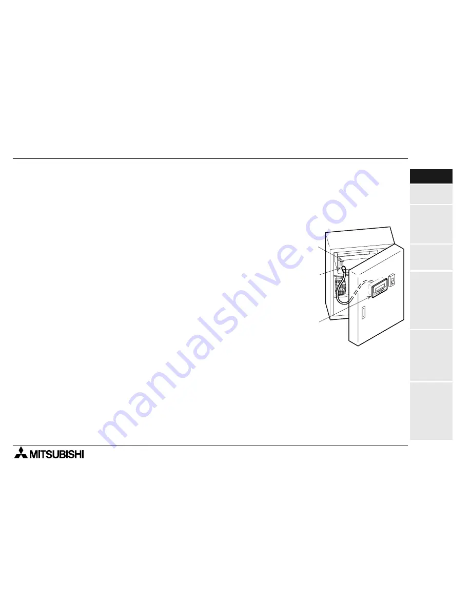
The 10DM is mounted on the surface of the control panel
or the operation panel, and connected to the program-
ming connector of the FX Series PLC located inside the
control panel or the operation panel.
The 10DM is a small display module with which you can
monitor word devices of the PLC and change the data
using the switches of the 10DM while looking at the dis-
play unit of the 10DM.

1.2

Features

1) The STN character type liquid crystal display unit with

LED backlight displays "16 characters x 2 lines", and
is easy to look at.

2) As to data registers (D), up to 2 points of 16- or 32-bit data can be displayed and changed in

signed decimal numbers.

3) As to counters (C) and timers (T), the current value and the set value can be displayed and

changed.

4) The setting of the entry monitor and the system setting information stored in the EEPROM

is held against power interruption.

FX Series

PLC

Programming

connector

10DM main

body

FX-10DM-E DISPLAY MODULE

Содержание MELSEC-F FX-10DM-E

Страница 1: ...USER S MANUAL FX 10DM E DISPLAY MODULE ...

Страница 2: ...empting to install or use the unit If in doubt at any stage of the installation of DISPLAY MODULE FX 10DM E always consult a professional electrical engineer who is qualified and trained to the local and national standards which apply to the installation site If in doubt about the operation or use of DISPLAY MODULE FX 10DM E please consult the nearest Mitsubishi Electric distributor This manual is...

Страница 3: ...ied here manufactured from January 1st 2002 FX 10DM E For this product see note under and over the page For more details please contact the local Mitsubishi Electric sales site Standard Remark EN50081 2 1993 Electromagnetic compatibility Generic emission standard Industrial environment Compliance with all relevant aspects of the standard Radiated Emissions and Mains Terminal Voltage Emissions EN61...

Страница 4: ...ion cables are used When using the FX 20P CAB0 EN cable the Earth Strap must be connected to a suitable earth point Ex 1 Table 0 1 DM Unit New Cables Existing Cables User Made Cables FX 10DM E From version A JY309C24571A of the FX 20P CAB0 EN FX 20P CAB0 modified as shown in EX 1 This cable need to be independently tested by the user to demonstrate EMC compatibility when they are used with Mitsubi...

Страница 5: ...FX 10DM E DISPLAY MODULE USER S MANUAL FX 10DM E DISPLAY MODULE Manual number JY992D86401 Manual revision C Date March 2003 ...

Страница 6: ...FX 10DM E DISPLAY MODULE iv ...

Страница 7: ...utomated equipment b Any commissioning or service engineer must be of a competent nature trained and qualified to the local and national standards required to fulfill that job These engineers should also be trained in the use and maintenance of the completed product This includes being completely familiar with all associated documentation for said product All maintenance should be carried out in a...

Страница 8: ...he symbols used will now be listed with a brief description of its meaning Hardware Warnings 1 Indicates that the identified danger WILL cause physical and property damage 2 Indicates that the identified danger could POSSIBLY cause physical and property damage 3 Indicates a point of further interest or further explanation Software Warnings 4 Indicates special care must be taken when using this ele...

Страница 9: ...uipment All examples and diagrams shown in this manual are intended only as an aid to understanding the text not to guarantee operation Mitsubishi Electric will accept no responsibility for actual use of the product based on these illustrative examples Please contact a Mitsubishi Electric distributor for more information concerning applications in life critical situations or high reliability ...

Страница 10: ...FX 10DM E DISPLAY MODULE viii ...

Страница 11: ... 6 Product configuration 1 8 1 6 1 Accessories 1 8 1 6 2 Options 1 8 1 7 Name of each part 1 9 1 8 Key functions and how to look at device indication 1 10 1 8 1 Key functions 1 10 1 8 2 How to look at device indication 1 12 2 Specifications 2 1 2 1 Outside dimensions 2 1 2 2 Power supply specifications 2 1 2 3 General specifications 2 2 2 4 Performance specifications 2 3 2 5 Connectable PLC 2 3 2 ...

Страница 12: ...ist 4 2 4 2 Functions offered in 10DM 4 3 5 Environmental Setting Function 5 1 5 1 Menu display 5 1 5 2 MONITOR SET 5 2 5 3 DEVICE RANGE 5 4 5 3 1 Description on setting screen and displayed contents 5 4 5 3 2 Operating procedure for DEVICE RANGE 5 5 5 4 DATA RANGE 5 7 5 4 1 Description on setting screen and displayed contents 5 7 5 4 2 Operating procedure for DATA RANGE 5 8 5 5 OTHER 5 9 5 5 1 Op...

Страница 13: ... 5 Creation of comments 6 15 6 3 6 Creation of messages 6 17 6 3 7 Setting program example 6 19 6 4 DEVICE MONITOR 6 21 6 5 Operating procedure for devices 6 23 6 5 1 Change of word devices for device monitor 6 23 6 5 2 Change of data in device monitor T 6 24 6 5 3 Change of data in device monitor D 6 25 6 5 4 Change of sign or of data 6 27 6 5 5 Operating procedure to release keyword 6 28 6 5 6 R...

Страница 14: ...FX 10DM E DISPLAY MODULE Contents xii ...

Страница 15: ... connector of the FX Series PLC located inside the control panel or the operation panel The 10DM is a small display module with which you can monitor word devices of the PLC and change the data using the switches of the 10DM while looking at the dis play unit of the 10DM 1 2 Features 1 The STN character type liquid crystal display unit with LED backlight displays 16 characters x 2 lines and is eas...

Страница 16: ... are provided to facilitate changes of data values 6 A word device name can be displayed in Katakana comment Katakana alphabet and numeric characters written in the PLC 7 ASCII codes can be stored in data registers of the PLC and the 10DM can be used as an easy message display unit ...

Страница 17: ...0DM offers the following two types of displays 1 Entry monitor display Refer to Paragraph 6 2 a Messages comments and word devices D T C can be displayed In the message display you can change the number of displayed characters from the PLC In the comment display comments in Katakana characters stored in a program in the PLC are displayed Up to 8 items can be displayed and scrolled with the and key...

Страница 18: ...All devices completely permitted Up to eight points can be set as the word device range between the minimum and maxi mum values No device completely prohibited Data range All devices completely permitted Up to eight points can be set as the word device range between the minimum and maxi mum values and the available data range No device completely prohibited 2 Reset function Refer to Paragraph 6 5 ...

Страница 19: ...CII codes Setting sheet Error mes sage list 3 Keyword release function Refer to Paragraph 6 5 5 When you try to change the data while the display function of the 10DM is used if a key word is set in a program in the PLC the keyword input screen shown in the figure below appears When the keyword you have input agrees with the one set in the PLC you can change the data You cannot change or invalidat...

Страница 20: ... A B indicates the operation to press the A and B keys at the same time If you press the A key at first then the B keys later for this expression buzzer sounds con tinuously to indicate that the input is invalid However when the CLR key is included in the expression such as A CLR press the A key at first then the CLR key soon For the detailed function of each key refer to Paragraph 1 8 1 Table 1 1...

Страница 21: ...sories of the 10DM Refer to Paragraph 1 6 Connect 10DM and FX Series PLC with cable Refer to Paragraph 3 2 Turn on the power of the 10DM Turn on the power of the PLC If FNC ENT are pressed COPYRIGHT C 2000 MITSUBISHI MELSEC FX 10DM E V1 00 Title screen To SYSTEM MODE To SYSTEM MODE The mode stored when power was turned off last time is displayed Second time or later First time after shipment To Se...

Страница 22: ...ng Compliance with the EMC requirement is approved with the cable FX 20P CAB0 EN For the action to be taken to any other cable refer to head page Table 1 2 Cable model name Application FX 20P CAB0 FX 20P CAB0 EN For FX0 FX0S FX1S FX0N FX1N FX2N FX2NC Series with mini DIN 8 pin connector FX 20P CAB For FX1 FX FX2C Series with D sub 25 pin connector FNC CLR ENT 10DM main body 1 Packing made of rubbe...

Страница 23: ...n 16 half width characters by 2 lines b CLR key Clears a device No or numeric value being input and returns to the initial status c FNC key Sets the line selection mode when pressed and held for 1 second or more While a numeric value is being input this key specifies the digit d and keys Decrease or increase a device No or numeric value and scroll the display line e ENT key Completes input of a de...

Страница 24: ...when pressed and held for 1 sec or more Allows to specify a digit by the numeric value of the device ENT Determines the input and changes over the mode from the line selection mode to the device selection mode Determines the device or completes the input of numeric value Moves up the function display on the SYSTEM MODE menu or shifts upward the display line of ENTRY MONITOR Changes over the device...

Страница 25: ...e to the initial status in which the cursor is not displayed Cancels the input Changes over the mode from the line selection mode in which the cursor flickers to the device selection mode in which the cursor _ is displayed Allows to input another device in DEVICE MONITOR FNC CLR Deletes the setting of the line where the cursor is located ENTRY MONITOR RANGE OK and DATA RANGE in MONITOR SET Reads t...

Страница 26: ...The example below shows display of each device using the device monitor function The entry monitor function can display the device name as comment Up to two data registers can be displayed Only one timer or counter can be displayed because both the current value and the set value are displayed for each timer or counter 1 The 10DM displays actually for a 16 bit type data register and for a 32 bit t...

Страница 27: ...ications 2 1 Outside dimensions 2 2 Power supply specifications Table 2 1 Supply voltage 5 V DC 5 supplied from FX Series PLC Power ripple 200 mV or less Current consumption 5V DC 220 mA Allowable instantaneous power interruption Operation shall continue against power interruption of less than 5 ms FNC CLR ENT 32 62 53 96 4 5 Unit mm Outer painting color Munsell 0 08GY 7 64 0 81 Mass 0 15 kg For a...

Страница 28: ...e 10 times in each of X Y and Z directions for 80 min When intermittent vibrations are applied 10 to 57 Hz 0 075 mm 57 to 150 Hz 9 8 m s2 When continuous vibrations are applied 10 to 57 Hz 0 035 mm 57 to 150 Hz 4 9 m s2 Impact resistance In conformance to JIS B 3502 and IEC 61131 2 147 m s2 3 times in each of X Y and Z directions Noise resistance By noise simulator of noise voltage 1 000 Vp p nois...

Страница 29: ...he PLC configuration For the details refer to the manual of the connected PLC Table 2 3 Display device and display colors STN character type liquid crystal character color black background color yellowish green Resolution and effective display size 80 16 dots 11 6 56 2 mm Displayed half width characters 16 half width characters 2 lines Visible angle range 30 degrees in left right up and down Opera...

Страница 30: ... FX Series PLC Table 2 5 Device name Maximum setting display range Data register D0 to D7999 16 bits 32768 to 32767 32 bits when used as a pair 2147483648 to 2147483647 D8000 to D8195 16 bits 32768 to 32767 Timer T0 to T199 100 ms 0 1 to 3276 7s T200 to T245 10 ms 0 01 to 327 67s T246 to T249 1 ms integrating type 0 001 to 32 767s T250 to T255 100 ms integrating type 0 1 to 3276 7s Counter C0 to C...

Страница 31: ...e panel face Install it using the following procedure 1 Dimensions inside the panel required for installation Consider the dimensions inside the panel shown in the right then process the mounting panel face and install the 10DM a PLC connection cable b Packing c Bracket 2 Processing the mounting panel face Drill the rectangular area shown in the left on the panel face At this time as shown in the ...

Страница 32: ... Attach a packing to the 10DM and insert it into the front face of the panel face a 10DM main body b Packing c Mounting area 4 Preparing the brackets Attach a tightening bolt b offered as accessory to each bracket a offered as accessory as shown in the right while paying attention to the direction a b c a b ...

Страница 33: ...r mes sage list 5 Fixing the 10DM A Insert the hook of each bracket offered as acces sory into the mounting hook hole of the 10DM and pull the hook toward you B Slide leftward each bracket and fix it C Tighten the screw until it is fixed with the tightening bolt offered as accessory Fix the 10DM at four points 2 points at the top and 2 points at the bottom a Bracket with tightening bolt Make sure ...

Страница 34: ...ramming connector of the FX Series PLC Because the power is supplied from the PLC to the 10DM through this cable wir ing for power supply is not required Connection procedure 1 Connecting the cable to the 10DM Hold the mini DIN 8 pin L shape connector of the accessory cable FX 20P CAB or FX 20P CAB0 EN by hand Align the mark with the direction of the notch on the connector for PLC of the 10DM and ...

Страница 35: ... case of FX 20P CAB Hold the other D sub 25 pin connector of the cable FX 20P CAB0 EN by hand Let the con nector be in the lateral direction and its longer edge be located on the upper side securely insert it completely In the case of FX 20P CAB0 and FX 20P CAB0 EN Hold the other mini DIN 8 pin connector of the cable FX 20P CAB0 EN by hand Align the mark with the direction of the notch on the prog...

Страница 36: ...lation Wiring and Maintenance 3 3 6 Connection examples of FX Series PLC FX 20P CAB0 FX 20P CAB0 EN Connected PLC FX0 FX0S FX1S FX0N FX1N FX2N FX2NC 10DM main body FX 20P CAB Connected PLC FX1 FX FX2C 10DM main body Programming port ...

Страница 37: ...y current of the 5V DC power supply If the total supply current exceeds the allowable capacity the 10DM cannot be connected 2 Operation of the 10DM after instantaneous power interruption The 10DM continues its operation against instantaneous power interruption of 5 ms or less If long power interruption of voltage drop has occurred the 10DM stops its operation And when the power is recovered the 10...

Страница 38: ...FX 10DM E DISPLAY MODULE Installation Wiring and Maintenance 3 3 8 MEMO ...

Страница 39: ...ONITOR SET OTHER 6 Display ENTRY MONITOR DEVICE MONITOR 7 Attachment ASCII codes Setting sheet Error mes sage list 4 SYSTEM MODE Menu The SYSTEM MODE menu allows diversified settings of the 10DM This menu offers 1 ENTRY MONITOR 2 DEVICE MONITOR for display and 3 MONI TOR SET and 4 OTHER for environmental setting FX 10DM E DISPLAY MODULE ...

Страница 40: ...u turn on the power while pressing and holding the FNC ENT keys in the power OFF status the SYSTEM MODE menu appears Change the numeric value with the cursor SYSTEM MODE menu by pressing the and keys to select a menu item Then press the ENT key to determine the selection ...

Страница 41: ...Reference Display 1 ENTRY MONITOR Allows to set in the unit of line monitoring of up to 8 items among the messages comments in Katakana characters and word devices D T and C set by the user Allows to change the current value D T and C and the set value T and C of word devices Message Arbitrary characters ASCII codes are dis played in data registers D of the PLC Comment Comments referred to as Kata...

Страница 42: ... available for the current value and the set value of word devices 5 2 4 OTHER 1 LANGUAGE allows to change over the lan guage for system settings between Japa nese and English 2 BUZZER allows to turn on and off issue of the key pressing confirmation buzzer 3 TITLE allows to display or hide the title screen which indicates the product model name the copyright etc 4 ALL SYSTEM allows to enable or di...

Страница 43: ...tting MONITOR SET OTHER 6 Display ENTRY MONITOR DEVICE MONITOR 7 Attachment ASCII codes Setting sheet Error mes sage list 5 Environmental Setting Function This section describes the functions of 3 MONITOR SET and 4 OTHER which allow to set the operating environment of the display functions of the 10DM 5 1 Menu display FX 10DM E DISPLAY MODULE ...

Страница 44: ...n 1 ENTRY MONITOR In addition 3 MONITOR SET allows to set restriction in the word device range in which the data can be changed and the numeric value range which can be input in 1 ENTRY MONI TOR and 2 DEVICE MONITOR Table 5 1 Display Description on function Reference paragraph 1 DISPLAY SET Allows to set up to 8 devices for messages and comments dis played in 1 ENTRY MONITOR 6 3 3 ...

Страница 45: ...h the data can be changed Setting Data values can be changed in all devices 1 RANGE OK You can set arbitrarily up to 8 device Nos 2 ERROR ALL DEV Data values cannot be changed in any device 5 3 3 DATA RANGE Allows to set the range 1 of word devices in which the data can be changed and set the range of numeric values which can be input as the data current values and set values Setting There is no r...

Страница 46: ...g which gives restriction can be set only to either one between DEVICE RANGE and DATA RANGE Either one should be set to 0 ALL OK 5 3 1 Description on setting screen and displayed contents This paragraph describes the contents displayed on the RANGE OK screen in DEVICE RANGE The minimum value and the maximum value of the item No which are once set are overwritten Change of only the maximum value is...

Страница 47: ... SYSTEM MODE Menu 5 Environ mental Setting MONITOR SET OTHER 6 Display ENTRY MONITOR DEVICE MONITOR 7 Attachment ASCII codes Setting sheet Error mes sage list 5 3 2 Operating procedure for DEVICE RANGE The example below shows a case in which D1000 to D2000 set to the item No 1 in RANGE OK in DEVICE RANGE is changed to D0 to D1000 ...

Страница 48: ...E Environmental Setting Function 5 5 6 Deleting the setting in DEVICE RANGE and DATA RANGE To delete the setting press the FNC key the press the CLR key soon while the cursor is flickering in a number indicating the device No ...

Страница 49: ...vice range in which the data can be changed in the same way as DEVICE RANGE described in the previous paragraph and the data range which can be input to word devices The setting which gives restriction can be set only to either one between DATA RANGE and DEVICE RANGE Either one should be set to 0 ALL OK 5 4 1 Description on setting screen and displayed contents This paragraph describes the content...

Страница 50: ...FX 10DM E DISPLAY MODULE Environmental Setting Function 5 5 8 5 4 2 Operating procedure for DATA RANGE ...

Страница 51: ...2 Display Description on major functions 1 LANGUAGE Allows to set the language used to display each menu item of SYSTEM MODE error messages etc Setting 1 JAPANESE 2 BUZZER Allows to set the buzzer sound issued once to confirm pressing of a key on the panel face and the buzzer sound for error issued consecutively twice Setting 1 OFF 3 TITLE Allows to set the title screen displayed when the power of...

Страница 52: ...isables the changeover by pressing FNC ENT 5 READ OUT COMM Searches for and stores the information on the location of the comment of a device to be displayed with regard to the comment written in the program area of the PLC Characters of the comment are not read out Setting 0 READ Reads out the comment Table 5 2 Display Description on major functions 0 OK Enables the changeover by pressing FNC ENT...

Страница 53: ...TEM MODE Menu 5 Environ mental Setting MONITOR SET OTHER 6 Display ENTRY MONITOR DEVICE MONITOR 7 Attachment ASCII codes Setting sheet Error mes sage list 5 5 1 Operating procedure for OTHER Change the numeric value with the cursor position by pressing the and keys to select a menu item Then press the ENT key to determine the selection ...

Страница 54: ...FX 10DM E DISPLAY MODULE Environmental Setting Function 5 5 12 MEMO ...

Страница 55: ...et Error mes sage list 6 Display Function The 10DM can offer display by 1 ENTRY MONITOR and 2 DEVICE MONITOR 6 1 Description on menu display and functions Change the numeric value with the cursor by pressing the and keys to select a menu item Then press the ENT key to determine the selection The user display selects and displays the contents set by the user and the devices displayed by key operati...

Страница 56: ...e SYSTEM MODE menu then the power is turned off are stored then displayed when the power is turned on next time 2 How to display the SYSTEM MODE menu Press the FNC and ENT keys at the same time If display of the SYSTEM MODE menu is prohibited by the environmental setting perform the following operation Turn off the power of the 10DM While pressing and holding the FNC and ENT keys at the same time ...

Страница 57: ...isplays messages and comments registered in advance as well as device names and data Table 6 1 Display Description on functions 1 ENTRY MONITOR Allows to specify in the unit of line up to 8 items of display in the form of mes sages comments in Katakana characters and word devices D T and C Allows to change the current value D T and C and the set value T and C of word devices Only two lines can be ...

Страница 58: ...ce name comment etc can be changed over to mes sage display by a program in the PLC This function is useful to messages on completion and error indication In the display example above the item No 6 indicates an example in which only a device is displayed because there are not comment and message data ...

Страница 59: ...ENTRY MONITOR setting sheet In addition write devices used in the setting and their occupation range 3 Design the character display specifications Paragraph 6 3 2 Learn the specifications of comments and messages and the restriction in display 4 Check the 10DM setting screen Paragraph 6 3 3 Read the explanation on the ENTRY MONITOR setting screen 5 Understand operations of the 10DM Paragraph 6 3 4...

Страница 60: ... C D and DD The device name and the data are displayed The preset word device D34 in this example is displayed A timer or counter is displayed in 2 lines For the details refer to the description on device monitor display Any sequence program is not required Table 6 2 Contents of setting Device Comment Message 1 MONITOR Device name Data 2 COMMENT Device name Data 1 3 VALUE ONLY Data only 4 MESSAGE ...

Страница 61: ...ices T C D and DD The comment and the data are displayed The comment of the preset word device D30 in this example is displayed If there is not a comment the device name is displayed in the same way as 1 MONITOR above Set the comment to D30 using the sequence programming tool then transfer it to the PLC 3 VALUE ONLY Target devices T C D and DD Only the data is displayed Only the data of the preset...

Страница 62: ... the displayed message If K 1 is written nothing is displayed blank display Program the device No storing the message and the ASCII codes for the message in the sequence program 5 MONITOR MES Target devices D and DD The device and the data are displayed then the displayed contents can be changed over to a message If D31 stores K 1 the device name and the data are displayed in the same way as 1 MON...

Страница 63: ...ces D and DD The comment the device and the data are displayed and the displayed contents can be changed over to a message If D31 stores K 1 the comment and the data are displayed in the same way as 2 COM MENT above If there is not comment the device name and the data are displayed in the same way as 1 MONITOR above Program the device No storing the message and the ASCII codes for the message in t...

Страница 64: ...get devices D and DD The data is displayed then the displayed contents can be changed over to a message Only the data is displayed in the same way as 3 VALUE ONLY above Program the device No storing the message and ASCII codes for the message in the sequence program ...

Страница 65: ... GUAGE in OTHER 2 Applicable PLC Comments can be set in the following PLC 3 Restriction in display The comment and the data are displayed in 1 line 16 characters as shown below This exam ple shows a case in which DD100 is set and the comment CONTROL is displayed If the data overlaps the comment the priority is given to the data Table 6 3 Display Number of characters Character type Applicable devic...

Страница 66: ...e 1 DISPLAY SET in 3 MONITOR SET on the SYSTEM MODE menu Description on the setting screen in the 10DM The contents displayed on the DISPLAY SET screen are described below The display setting and the device of the item No set once are overwritten You can delete the setting in the unit of item No For the operating procedure refer to the description on the setting of DEVICE RANGE ...

Страница 67: ...allation Wiring Maintenance 4 SYSTEM MODE Menu 5 Environ mental Setting MONITOR SET OTHER 6 Display ENTRY MONITOR DEVICE MONITOR 7 Attachment ASCII codes Setting sheet Error mes sage list 6 3 4 Operating procedure for ENTRY MONITOR In the example T5 and VALUE ONLY are set to the item No 4 ...

Страница 68: ... MODULE Display Function 6 6 14 Deleting the setting in DISPLAY SET If you would like to delete an item make sure that the cursor is flickering in the item No to be deleted press the FNC key then press the CLR key soon ...

Страница 69: ...mes sage list 6 3 5 Creation of comments You should create comments using the programming software The table below shows representative programming tools For the details of the operating procedure and the specifications of each software above refer to the corresponding manual Table 6 5 Programming software model name Comment creation function name Version FX PCS AT EE Comment FX PCS WIN E Device c...

Страница 70: ...ist in View Com ment view Device comment Device name then input a comment Execute PLC Transfers Write 5 Store the comment information of the 10DM Search for the comment information using the READ OUT COMM function in OTHER on the SYSTEM MODE menu in the 10DM Setting procedure The 10DM searches for and stores the information on locations of the comment of the device written in the memory of the PLC...

Страница 71: ...etting and the device 2 Convert character strings to be displayed into ASCII codes in accordance with the ASCII table 3 Assign characters to data registers as follows Characters are displayed in the order of upper 8 bits lower 8 bits of data registers Table 6 6 Item No Device Display setting 1 D0 4 MESSAGE Table 6 7 Display example ASCII code hexadecimal Assignment Production 50 72 6F 64 75 63 74 ...

Страница 72: ...igned using the MOV instruction FNC 12 5 Make a sequence program which changes over displayed character strings MOV H5072 D100 MOV H6F64 D101 MOV H7563 D102 MOV H7469 D103 Pr od uc t i MOV H6F6E D104 on MOV H0000 D105 end In the same way make a program which writes 2 OPERATION to D110 MOV K100 D00 MOV K110 D00 K100 D100 D00 Selects 1 PRODUCTION K110 D110 D00 Selects 2 OPERATION ...

Страница 73: ...e 1 Setting in the 10DM Table 6 8 Setting in ENTRY MONITOR Display in 10DM Remarks Item Set value ASCII codes Refer to attachment Sequence program 1 No 1 D200 4 MESSAGE Control Co H436F nt H6E74 ro H726F l H6C00 a Write ASCII codes shown on the left to data regis ters D100 and later b Write the data register data No K100 of the message to be displayed to D200 2 No 2 D202 2 COMMENT Number 1234 Use ...

Страница 74: ...PLAY MODULE Display Function 6 6 20 2 Example of sequence program 0 MOV H436F D100 Co MOV H6E74 D101 nt MOV H726F D102 ro MOV H6C00 D103 l MOV K100 D200 b Specifies the data register No 100 END a Writes ASCII codes ...

Страница 75: ...dures Display example When specifying the device No or data press the key to increase it and press the key to decrease it When the or key is pressed and held the device No or data increases or decreases quickly Use the FNC key to specify the digit Table 6 9 Display Description on functions 2 DEVICE MONITOR Allows to select word devices D T and C of the PLC and display and change the current value ...

Страница 76: ...ers you have input agree with the keyword set in the PLC the keyword is released and you can change the current value D T and C and the set value T and C of word devices After you input characters and press the ENT key the keyword remains released until the power of the 10DM is turned on You do not have to input any character for releasing the keyword again as far as the power of the 10DM remains ...

Страница 77: ...OR 7 Attachment ASCII codes Setting sheet Error mes sage list 6 5 Operating procedure for devices 6 5 1 Change of word devices for device monitor This paragraph describes the procedure to specify word devices Because a timer T occupies 2 lines it is displayed as shown in the lowest screen above A counter C is dis played in the same way In the case of a data register D or DD it is displayed in the ...

Страница 78: ...FX 10DM E DISPLAY MODULE Display Function 6 6 24 6 5 2 Change of data in device monitor T This paragraph describes the operating procedure to change the set value of a timer ...

Страница 79: ...uction 2 Specifica tions 3 Installation Wiring Maintenance 4 SYSTEM MODE Menu 5 Environ mental Setting MONITOR SET OTHER 6 Display ENTRY MONITOR DEVICE MONITOR 7 Attachment ASCII codes Setting sheet Error mes sage list 6 5 3 Change of data in device monitor D ...

Страница 80: ... MODULE Display Function 6 6 26 When you press the CLR key in the setting mode shown above the 10DM returns to the normal mode At this time the data whose setting is not completed is canceled and not written to the PLC ...

Страница 81: ...umeric value by pressing the or key However it takes consid erable time to set a large numeric value Current value 2 1 0 1 2 Cautions on key operation When you change the sign by pressing the or key then press the or key the 10DM performs the following operation For example when you have set the sign to minus by mistake and would like to return the sign to plus When you have set the sign to minus ...

Страница 82: ...o change the data the key word input request message appears to ask you to input the keyword By the procedure above the keyword set in the PLC is temporarily released In order to validate the keyword again turn off the power of the 10DM once Then the keyword stored in the memory inside the 10DM is cleared and the keyword set in the PLC becomes effective again ...

Страница 83: ...nt value of a data register by writing K0 to it Target devices D DD T current value and C current value If a word device to be reset uses a data register D timer T or counter C in a sequence program especially when it uses a data register the word device may not be overwritten In such a case the program may set some data to the word device using the MOV instruction etc in the program The word devi...

Страница 84: ...FX 10DM E DISPLAY MODULE Display Function 6 6 30 MEMO ...

Страница 85: ...ers ASCII codes The tables below show characters which can be displayed in messages and comments in the ENTRY MONITOR function in the 10DM and the corresponding ASCII codes For an ASCII code not shown in the tables below space is displayed Only in the case of K0 H00 however it is regarded as the end of the line and the proceeding data is not displayed blank display The lower line in each column sh...

Страница 86: ...s sheet and fill it in Each of data registers D and messages requires 1 line in display Each of timers T and counters C requires 2 lines in display Item No Example Write down the layout of displayed characters P r o d u c t i o n 1 2 3 4 5 6 7 8 9 10 11 12 13 14 15 16 T20 0 00s S00 0s 1 MESSAGE 2 D55 1234 3 COMMENT D0 1234 4 Item No ...

Страница 87: ...ither one among D DD T and C 2 COMMENT Occupies either one among D DD T and C 3 VALUE ONLY Occupies either one among D DD T and C 4 MESSAGE Occupies D and D 1 or DD and DD 1 5 MONITOR MES Occupies D and D 1 or DD and DD 1 6 COMMENT MES Occupies D and D 1 or DD and DD 1 D DD T C D DD T C 50 D DD T C D DD D DD 100 101 D DD D DD 200 201 202 203 D DD T C D DD T C D DD T C D DD T C D DD T C D DD T C D ...

Страница 88: ... 10DM sides 2 Check whether there are no abnormalities such as flaws on the cable or damages in the connectors Er1 DEVICE No The word device No you have input is beyond the range built in the connected PLC Confirm the device specifications of the PLC and observe the allowable range Supplement The FX1 FX FX2N FX2NC Series is checked However the FX0 FX0S FX0N FX1S Series is regarded as the FX Series...

Страница 89: ...1000 or later from the 10DM while an EEPROM memory cassette is mounted in the PLC Write is disabled Replace the EEPROM memory cassette with an RAM mem ory cassette Er5 INPUT DATA You input a value beyond the allowable data range to a word device The allowable data range varies depending on the word device type This error does not occur usually because the 10DM checks the range of each input value ...

Страница 90: ...FX 10DM E DISPLAY MODULE Attachment 7 7 6 MEMO ...

Страница 91: ......

Страница 92: ...DG MARUNOUCHI TOKYO 100 8310 HIMEJI WORKS 840 CHIYODA CHO HIMEJI JAPAN JY992D86401C MEE Effective Mar 2003 Specification are subuject tochange without notice USER S MANUAL FX 10DM E DISPLAY MODULE MODEL FX 10DM U E MODEL CODE 09R911 ...

Отзывы: