Installation, Wiring and Maintenance 3
3-1
1.Introduction
2.Specifica-
tions
3.Installation
Wiring
Maintenance
4."SYSTEM
MODE"
Menu
5.Environ-
mental
Setting
"MONITOR
SET"
"OTHER"
6.Display
"ENTRY
MONITOR"
DEVICE
MONITOR
7.Attachment
ASCII codes
Setting sheet
Error mes-
sage list
3.
Installation, Wiring and Maintenance
This section describes the panel processing, installation and wiring procedures for the 10DM.
3.1
Installation
The 10DM is to be embedded on the panel face. Install it using the following procedure.
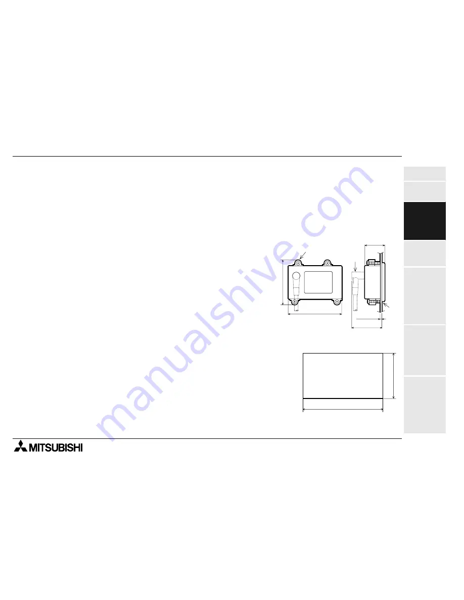
1) Dimensions inside the panel required for installation
Consider the dimensions inside the panel shown in the
right, then process the mounting panel face and install
the 10DM.
a) PLC connection cable
b) Packing
c) Bracket
2) Processing the mounting panel face
Drill the rectangular area shown in the left on the panel face.
At this time, as shown in the figure in 1) above, the space for
brackets (10 mm) is required above and below the mounting
area.
* Make sure that the mounting panel face thickness is 5 mm
or less.
5 ms
or less
86
32
73
49
b)
a)
c)
87
+1
0
54
+1 0
Panel cut area
Unit: mm
FX-10DM-E DISPLAY MODULE
Содержание MELSEC-F FX-10DM-E
Страница 1: ...USER S MANUAL FX 10DM E DISPLAY MODULE ...
Страница 6: ...FX 10DM E DISPLAY MODULE iv ...
Страница 10: ...FX 10DM E DISPLAY MODULE viii ...
Страница 14: ...FX 10DM E DISPLAY MODULE Contents xii ...
Страница 38: ...FX 10DM E DISPLAY MODULE Installation Wiring and Maintenance 3 3 8 MEMO ...
Страница 50: ...FX 10DM E DISPLAY MODULE Environmental Setting Function 5 5 8 5 4 2 Operating procedure for DATA RANGE ...
Страница 54: ...FX 10DM E DISPLAY MODULE Environmental Setting Function 5 5 12 MEMO ...
Страница 84: ...FX 10DM E DISPLAY MODULE Display Function 6 6 30 MEMO ...
Страница 90: ...FX 10DM E DISPLAY MODULE Attachment 7 7 6 MEMO ...
Страница 91: ......


