3
Controller
Names of each part
3-38
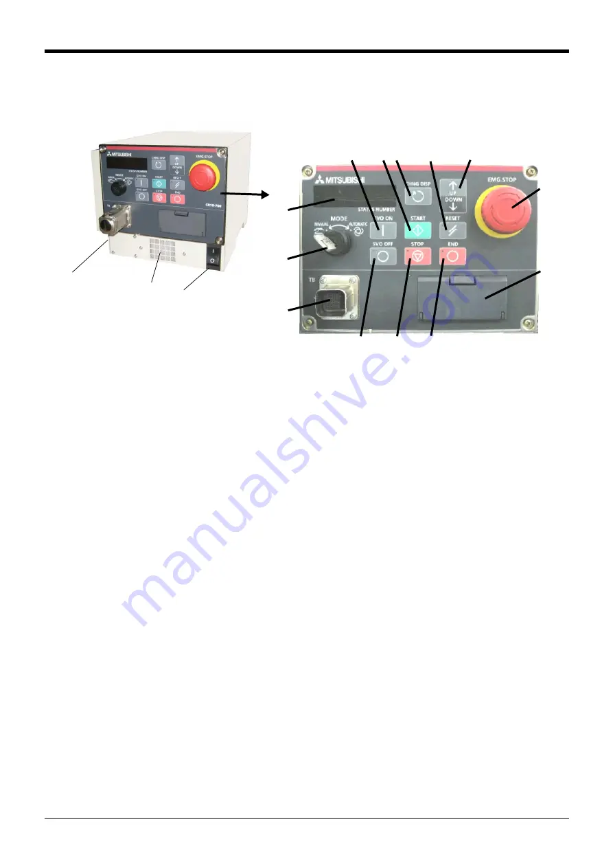
Fig.3-2 : Names of drive unit parts (CE marking specification)
①
POWER switch.................................. This turns the control power ON/OFF. (With earth leakage breaker function)
* 1)
②
START button....................................This executes the program and operates the robot. The program is run continuously.
③
STOP button ......................................This stops the robot immediately. The servo does not turn OFF.
④
RESET button ....................................This resets the error. This also resets the program's halted state and resets the program.
⑤
Emergency stop switch..................This stops the robot in an emergency state. The servo turns OFF.
⑥
CHNGDISP button ...........................This changes the details displayed on the display panel in the order of "Override" → "Pro
-
gram No." → "Line No.".
⑦
END button..........................................This stops the program being executed at the last line or END statement.
⑧
SVO.ON button..................................This turns ON the servo power. (The servo turns ON.)
⑨
SVO.OFF button ............................... This turns OFF the servo power. (The servo turns OFF.)
⑩
STATUS NUMBER
(display panel).....................................The alarm No., program No., override value (%), etc., are displayed.
⑪
T/B connection connector .........This is a dedicated connector for connecting the T/B.
When not using T/B, connect the
attached dummy connector.
⑫
MODE key switch .............................This changes the robot's operation mode.
AUTOMATIC................................operations from the controller or external equipment are valid. Operations for
which the operation mode must be at the external device or T/B are not possible. It
is necessary to set the parameter for the rights of operation to connection
between the operation panel and external equipment. For details, please refer to
"INSTRUCTION MANUAL/Detailed explanations of functions and operations" of
the separate volume.
MANUAL........................................When the T/B is valid, only operations from the T/B are valid. Operations for
which the operation mode must be at the external device or controller are not pos
-
sible.
⑬
UP/DOWN button ............................This scrolls up or down the details displayed on the "STATUS. NUMBER" display panel.
⑭ Interface cover...........................Unused in this drive unit. Please use closing this cover, because of to prevent
deterioration of protection performance.
⑮ Terminal cover (CR1QA-700 series)
..................................................The terminal which connects the primary power cable.
⑯ Filter (intake vent) ....................The intake vent of the recirculating air for internal cooling.
*1)The power switch of DU1A-771-S15/S16 can be locked by installing the padlock etc. Please prepare the
padlock by the customer. Padlock specification is shown in
Page 39, "(1) Padlock specification"
[Note] The RS232 connection connector is not prepared by this controller. If you use it, please prepare sequencer
CPU or the unit corresponding to the sequencer
<DU1A-771-S15/S16>
CE marking specification
①
②
④
⑤
⑥
⑧
⑬
⑫
⑩
⑨
⑭
⑦
③
⑪
<Operating panel>
⑮
Power cable
clamp
(Side)
⑯
Содержание MELFA SQ Series
Страница 2: ......
Страница 11: ...Contents iii Page 7Appendix Appendix 98 Appendix 1 Specifications discussion material Appendix 98 ...
Страница 110: ......
Страница 111: ......
Страница 112: ......
Страница 113: ......
Страница 114: ......
Страница 115: ......
Страница 116: ......
Страница 117: ......
Страница 118: ......
Страница 119: ......
Страница 120: ......
Страница 121: ......
Страница 122: ......
Страница 123: ......
Страница 124: ......
Страница 125: ......
Страница 126: ......
Страница 127: ......
Страница 128: ......
Страница 129: ......
Страница 130: ......
Страница 131: ......
Страница 132: ......
Страница 133: ......
Страница 134: ......
Страница 135: ......
Страница 136: ......
Страница 137: ......


