background image

-

 131 

-

'19 • SCM-SM-276

Error code

Remote control:

LED

Green

Red

Indoor

Outdoor

Content

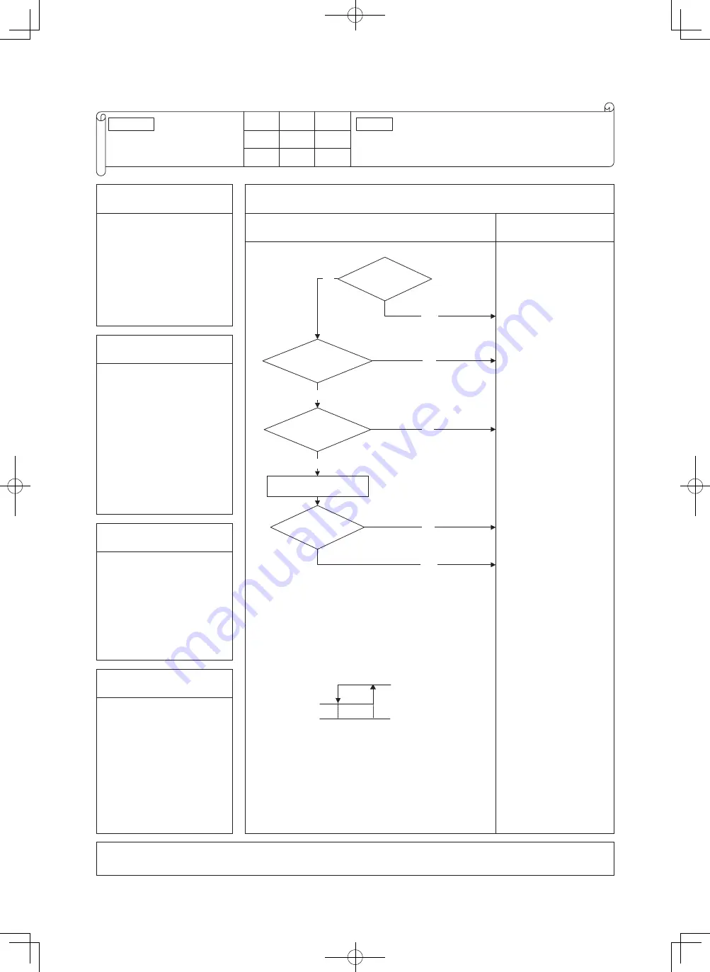
E8

Heating overload operation

Keeps flashing

1

-

time flash

Stays OFF

1. Applicable model

5. Troubleshooting

All models

Diagnosis

Countermeasure

NO

YES

(2)

Is the air filter clogged?

Is the 

indoor heat exchanger 

temperature sensor

connection OK?

Are the 

characteristics of indoor 

heat exchanger temperature 

 sensor OK?

NO

Check the error data with the 

remote control.

YES

Is the unit 

operating in the state of 

heating overload?

Note (1) Judge if it is in the state of overload or not as follows.


Is there any short-circuit of air?


Isn’t there any fouling or clogging on the indoor heat exchanger?


Is the outdoor fan control normal?


Isn't the room and outdoor air temperature too high?

Note (2) For characteristics of indoor heat exchanger temperature  sensor, 

  see the error display E6.

YES

NO

YES

NO

Error stop

Reset

Indoor heat exchanger temperature (°C)

56   


 63  

Wash.

Defective indoor heat 

exchanger temperature 

sensor connector

Correct.

Defective indoor heat 

exchanger temperature 

sensor.

Check refrigerant system.

Adjust.

2. Error detection method

Indoor heat exchanger 

temperature sensor (Thi-R1, R2, 

R3)

3. Condition of error displayed

When it is detected 5 times 

within 60 minutes from initial 

detection or when the overload 

condition is detected for 6 

minutes continuously.

4. Presumable cause

• Clogged air filter

• Defective indoor heat 

exchanger temperature sensor 

connector

• Defective indoor heat 

exchanger temperature sensor

• Anomalous refrigerant system

Note:

 During heating operation; After starting compressor, compressor rotation speed is decreased by detecting indoor heat 

exchanger temperature (Thi-R) in order to control high pressure. 

Содержание SRK60ZSX-W

Страница 1: ... W INDOOR UNIT Wall mounted type SRK20ZSX W WB WT Duct connected Low Middle static pressure type FDUM50VH SRK71ZR W 25ZSX W WB WT 35ZSX W WB WT 50ZSX W WB WT 60ZSX W WB WT SRK20ZS W WB WT 25ZS W WB WT 35ZS W WB WT 50ZS W WB WT 4 way ceiling cassette type FDTC25VH 35VH 50VH 60VH Ceiling concealed type SRR25ZM W 35ZM W 50ZS W 60ZS W Ceiling suspended type FDE50VH ...

Страница 2: ......

Страница 3: ...ge setting 13 13 Night setback operation 13 9 5 Selection of the annual cooling function 14 16 AUTO OFF operation 14 15 Display brightness adjustment 19 Protective control function 15 18 Outline of automatic operation 15 14 17 Outline of dehumidifying DRY operation 18 1 1 2 SRK ZS series 4 Installing two air conditioners in the same room 18 3 Auto restart function 2 Unit ON OFF button 18 17 1 Oper...

Страница 4: ...mer operation 31 8 Air flow direction adjustment 29 28 6 High power operation 28 7 Economy operation 11 Silent operation 31 12 Night setback operation 31 15 Outline of automatic operation 33 16 Protective control function 34 37 1 1 4 SRR series 4 Installing two air conditioners in the same room 36 3 Auto restart function 2 Unit ON OFF button 36 35 1 Operation control function by wireless remote co...

Страница 5: ... 49 8 Thermostat operation 53 7 Auto swing control FDTC and FDE only 52 55 55 56 55 56 57 56 57 58 12 Drain pump motor DM control 11 Drain pump control 15 Heating overload protection 13 Operation check drain pump test run operation mode 14 Cooling dehumidifying frost protection 18 High ceiling control 16 Anomalous fan motor 17 Plural unit control Control of 16 units group by one remote control 19 ...

Страница 6: ...ntrol RC EX3A only 65 35 Indoor unit overload alarm RC EX3A only 64 64 32 Fan circulator operation RC EX3A only 33 The operation judgment is executed every 5 minutes RC EX3A only 64 1 Cooling overload protective control 70 6 Heating low outdoor temperature protective control 73 8 Service valve gas side closing operation 7 Refrigeration cycle system protective control 73 72 70 4 Heating high pressu...

Страница 7: ... 82 90 7 Inspection procedures corresponding to detail of trouble 9 Checking the indoor electrical equipment 96 8 Phenomenon observed after short circuit wire breakage on sensor 95 11 Inspection procedure for blown fuse on the indoor and outdoor unit PCB 97 97 10 How to make sure of wireless remote control 6 Inverter checker for diagnosis of inverter output 110 4 Troubleshooting at the outdoor uni...

Страница 8: ... 6 19 SCM SM 276 3 ELECTRICAL WIRING 156 4 PIPING SYSTEM 164 2 2 2 Troubleshooting flow 111 112 2 Troubleshooting 1 List of troubles 111 7 Outdoor unit inspection points 110 ...

Страница 9: ...t time and timer function ACL switch This switch resets the program to default state PROGRAM button This button sets WEEKLY TIMER HI ECO button This button changes the HIGH POWER ECO operation AIR FLOW LEFT RIGHT button This button changes the air flow left right direction SILENT button This button sets the SILENT operation OFF TIMER button This button selects OFF TIMER operation WEEKLY button Thi...

Страница 10: ...remote control and indoor unit a ࠉSetting the wireless remote control i Pull out the cover and take out batteries ii Disconnect the switching line next to the battery with wire cutters iii Insert batteries Close the cover b ࠉSetting indoor unit i Turn off the power source and turn it on after 1 minute ii Point the wireless remote control that was set according to the procedure described on the lef...

Страница 11: ...peration for 15 minutes continuously The wireless remote control displays HIGH POWER mark and the FAN SPEED display disappears a During the HIGH POWER operation the room temperature is not controlled When it causes an excessive cooling and heating press the HI ECO button again to cancel the HIGH POWER operation b HIGH POWER operation is not available during the DRY and the ON timer to OFF timer op...

Страница 12: ...ETBACK botton is pressed c Not operable while the air conditioner is OFF d The setting temperature is adjusted according to the following table at the start of operation one hour after the start of operation two hours after the start of operation Temperature adjustment Cooling Heating 0 5 1 0 1 0 2 0 1 5 2 5 Mode Item Notes 1 It will go into economy operation at the next time the air conditioner r...

Страница 13: ...ter Right approx 50 Right approx 20 Right approx 30 Right approx 45 Right approx 50 Louver stopped Swing Spot Wide In HEAT operation In COOL DRY FAN operation Every time when you press the AIR FLOW L R Left approx 50 Left approx 50 Left approx 20 Left approx 20 Left approx 45 Center Approx 20 Approx 30 Approx 55 Approx 25 Approx 55 b Louver c Swing i ii d Memory flap Flap or louver stopped COOL DR...

Страница 14: ...5 C Setting temp Room temp 5 C Setting temp Room temp 5 C HIGH POWER AUTO HI MED LO HIGH POWER AUTO Flap Louver Cooling Up down swing Heating Wide Fixed Center Fixed Flap Louver Cooling Heating Left right swing Horizontal blowing Fixed Slant forwardl blowing Fixed Flap Louver Cooling Heating Wide Fixed Flap Louver Cooling Heating Horizontal blowing Fixed Slant forwardl blowing Fixed Operation mode...

Страница 15: ...c OFF timer operation 14 Air flow range setting a Setting i If the air conditioner is running press the ON OFF button to stop ii Press the AIR FLOW U D UP DOWN button and the AIR FLOW L R LEFT RIGHT button together for 5 seconds or more iii Setting the air flow range iv Press the ON OFF button Air flow range Air flow range Air flow range Left end installation Center installation Right end installa...

Страница 16: ...ghtness of unit display Note 1 When the unit displays self diagnosis or service mode brightness level is always LV2 Brightness level Run light Timer light LV2 50 0 LV1 LV0 100 50 0 100 17 Outline of dehumidifying DRY operation The purpose is Dehumidification and not to control the humidity to the target condition Indoor outdoor unit control the operation condition to reduce the humidity and also p...

Страница 17: ...ps 12 34rps ECO Heating Cooling SP Setting temperature SP Indoor air temperature C 28 Outdoor air temperature C b Operation mode is changes when keep cooling and heating thermostat off 20 minutes and be satisfied following conditions If the setting temperature is changed with the remote control the operation mode is judged immediately c When the unit is started again within one hour after the stop...

Страница 18: ...il of anti frost operation iii Reset conditions Indoor heat exchanger temperature C 2 5 5 8 0 rps c Cooling overload protective control i Operating conditions ii Detail of operation Indoor heat exchanger temperature Item 5 C or lower 2 5 C or lower Compressor command speed Indoor fan Outdoor fan 4 way valve Item SRK20 25 35ZSX S Outdoor air temperature Lower limit speed Model 1 2 1 2 1 2 1 2 iii R...

Страница 19: ...ENU switch This switch selects the CLEAN operation display brightness adjustment and PRESET operation ON TIMER button This button selects ON TIMER operation TIMER button This button is used for setting the current time and timer function ACL switch This switch resets the program to default state PROGRAM button This button sets WEEKLY TIMER HI ECO button This button changes the HIGH POWER ECONOMY o...

Страница 20: ...re not operated with one wireless remote control Set the wireless remote control and indoor unit a ࠉSetting the wireless remote control i Pull out the cover and take out batteries ii Disconnect the switching line next to the battery with wire cutters iii Insert batteries Close the cover b ࠉSetting an indoor unit i Turn off the power source and turn it on after 1 minute ii Point the wireless remote...

Страница 21: ...ration for 15 minutes continuously The wireless remote control displays HIGH POWER mark and the FAN SPEED display disappears a During the HIGH POWER operation the room temperature is not controlled When it causes an excessive cooling and heating press the HI POWER ECONOMY button again to cancel the HIGH POWER operation b HIGH POWER operation is not available during the DRY and the ON timer to OFF ...

Страница 22: ... a soft operation with the power suppressed in order to avoid an excessive cooling or heating The unit operate 1 5 higher than the setting temperature during cooling or 2 5 lower than that during heating The wireless remote control displays ECONOMY mark and the FAN SPEED display disappears a It will go into ECONOMY operation at the next time the air conditioner runs in the following cases When the...

Страница 23: ...B 087D 10 3D auto operation a i ii Cooling Air flow selection Operation mode AUTO HI MED LO Heating Room temp Setting temp 5 C Room temp Setting temp 5 C Setting temp Room temp 5 C Setting temp Room temp 5 C HIGH POWER AUTO HI MED LO HIGH POWER AUTO Flap Louver Cooling Up down swing Heating Wide Fixed Center Fixed Flap Louver Cooling Heating Left right swing Horizontal blowing Fixed Slant forwardl...

Страница 24: ...nd the compressor speed 13 Night setback operation When the night setback operation is set the heating operation starts with the setting temperature at 10 Outdoor fan speed Upper limit Compressor speed Upper limit Cooling Heating Cooling Heating SCM71 SCM80 4th speed 40 rps 4th speed 55 rps 4th speed 45 rps 4th speed 60 rps b Flap Louver Cooling Heating Left right swing Horizontal blowing Fixed Sl...

Страница 25: ...This function can be used when it is necessary to adjust the brightness of unit display Note 1 When the unit displays self diagnosis or service mode brightness level is always LV2 Brightness level Run light Timer light LV2 50 0 LV1 LV0 100 50 0 100 b Sleep timer operation c OFF timer operation 14 Air flow range setting a Setting i If the air conditioning unit is running press the ON OFF button to ...

Страница 26: ...diately c When the unit is started again within one hour after the stop of automatic operation or when the automatic operation is selected during heating cooling or dehumidifying operation the unit is operated in the previous operation mode d Setting temperature can be adjusted within the following range There is the relationship as shown below between the signals of the wireless remote control an...

Страница 27: ...eset conditions 47 C or more 35 rps The lower limit of compressor speed is set to 30 or 40 model SRK50 29 or 35 rps However when the thermo OFF the speed is reduced to 0 rps The outdoor fan is stepped up by 3 speed step Upper limit 7 model SRK50 8 th speed When the outdoor air temperature TH2 has become continuously for 30 seconds at 41 C or more or 47ºC or more with the compressor running the low...

Страница 28: ...mer function Switch for resetting microcomputer This button sets WEEKLY TIMER This button changes the HIGH POWER ECONOMY operation This button changes the air flow left right direction This buttion changes the SILENT operation This button selects OFF TIMER operation This button switches the WEEKLY TIMER to ON OFF Each time the button is pressed the fan speed changes This button sets 3D AUTO operat...

Страница 29: ...he cover b ࠉSetting an indoor unit i Turn off the power source and turn it on after 1 minute ii Point the wireless remote control that was set according to the procedure described on the left side at the indoor unit and send a signal by pressing the ACL switch on the wireless remote control Since the signal is sent in about 6 seconds after theACL switch is pressed point the wireless remote control...

Страница 30: ...will start from the set time d When the following operation are set HIGH POWER operation will be cancelled When the HI ECO button is pressed again The operation mode will be changed to the ECONOMY operation When the operation mode is changed When it has been 15 minutes since HIGH POWER operation has started When the 3D AUTO botton is pressed When the SILENT botton is pressed When the NIGHT SETBACK...

Страница 31: ...MY operation at the next time the air conditioner runs in the following cases When the air conditioner is stopped by ON OFF button during ECONOMY operation When the air conditioner is stopped in SLEEP or OFF TIMER operation during ECONOMY operation When the operation is retrieved from CLEAN or ALLERGEN CLEAR operation b When the following operation are set ECONOMY operation will be canceled When t...

Страница 32: ... cooling and heating i ii Cooling Air flow selection Operation mode AUTO Heating Indoor temp Setting temp 5 C Indoor temp Setting temp 5 C Setting temp Indoor temp 5 C Setting temp Indoor temp 5 C HIGH POWER AUTO HI HI MED MED ULO ULO LO LO HIGH POWER AUTO Flap Louver Cooling Up down swing Heating Wide Fixed Center Fixed Flap Louver Cooling Heating Left right swing Horizontal blowing Fixed Slant f...

Страница 33: ...ting a Setting i If the air conditioning unit is running press the ON OFF button to stop ii Press the AIR FLOW U D UP DOWN button and the AIR FLOW L R LEFT RIGHT button together for 5 seconds or more iii Setting the air conditioning installation location Center installation L R The unit starts the operation 5 to 60 minites earlier so that the room can approach optimum temperature at ON timer L R R...

Страница 34: ... AIR FLOW U D UP DOWN button and the AIR FLOW L R LEFT RIGHT button together for 5 seconds or more iii Setting the air conditioning installation location iv Press the ON OFF button Air flow range Air flow range Air flow range Left end installation Center installation Right end installation Center installation L R L R Right end installation Left end installation wireless i iv ii iii ii ...

Страница 35: ...ting temperature with the remote control the hourly judgment of operation mode is cancelled 09 SRK DB 087D b i ii iii c d 27 5 25 5 18 0 18 30 15 ࠉOutline of cooling operation a ࠉOperation of major functional components in cooling mode b Detail of control in each mode Pattern 1 Fuzzy operation ON OFF OFF OFF OFF OFF ON OFF few minutes ON OFF few minutes ON ON ON OFF Thermostat ON Thermostat OFF Fa...

Страница 36: ...RK63 71 80ZM S Outdoor air temperature Lower limit speed Model 1 2 1 1 2 more with the compressor running the lower limit The lower limit of compressor command speed is set to 30 or 40 rps and even if the calculated result becomes lower than that after fuzzy calculation the speed is kept to 30 or 40 rps However when the thermo OFF the speed is reduced to 0 rps 40 41 46 47 ON1 OFF ON2 Outdoor air t...

Страница 37: ...Press to start operation press again to stop This button sets the room temperature This button changes the air flow up down direction This switch is for setting the time This button selects SLEEP operation This switch selects the CLEAN operation This button selects ON TIMER operation This buttions is used for setting the cur rent time and timer function Switch for resetting microcomputer This butt...

Страница 38: ...Louver Timer switch COOL About 24ºC Auto Auto Continuous DRY About 25ºC HEAT About 26ºC Unit ON OFF button a Auto restart function records the operational status of the air conditioner immediately prior to be switched off by a power cut and then automatically resumes operations after the power has been restored b The following settings will be cancelled i Timer settings ii HIGH POWER operations No...

Страница 39: ...e wireless remote control i Pull out the cover and take out batteries ii Disconnect the switching line next to the battery with wire cutters iii Insert batteries Close the cover b ࠉSetting an indoor unit i Turn off the power source and turn it on after 1 minute ii Point the wireless remote control that was set according to the procedure described on the underside at the indoor unit and send a sign...

Страница 40: ...H POWER operation has started e Not operable while the air conditioner is OFF f After HIGH POWER operation the sound of refrigerant flowing may be heard մ When the SILENT botton is pressed յ When the NIGHT SETBACK botton is pressed 7 Economy operation Pressing the HI POWER ECONO button initiate a soft operation with the power suppressed in order to avoid an excessive cooling or heating The unit op...

Страница 41: ...switch ON Cooling switch ON Heating switch ON Operation Operation Operation Operation Operation Example of operating pattern Note 1 indicates currect operation First operation Second operation Notes Selected mode Cooling Heating Example 1 2 Remote control display COOL HEAT Operation COOL HEAT Selected mode Heating Cooling Remote control display HEAT COOL Different mode is only fan operation Operat...

Страница 42: ...difying Cooling Indoor air temperature C Outdoor air temperature C A b i ii iii c d Signals of wireless remote control Display on the a Determination of operation mode 13 Outline of automatic operation b Outline of control i Indoor unit fan speed and compressor are controlled by the area which is selected by the temperature difference ii The indoor unit check the current area by every 5 minutes an...

Страница 43: ...h is activated later has priority and can start and stop the operation When the jumper wire J3 is released Permission Prohibition mode When CnT input is set to ON the operation mode is changed to permission and if input is set to OFF the operation is prohibited When the jumper wire J1 is short circuited The signal a above starts the air conditioner Shipping status When the jumper wire J1 is releas...

Страница 44: ...ration instruction Depends on operation mode 8 2 5 i ii Reset Protective control CnT Input Unit CASE A Unit CASE B OFF OFF ON ON ON ON OFF OFF OFF ON ON ON OFF OFF OFF Note 1 The ON with the mark indi cates an ON operation using the wired remote control etc ON i Level input If the factory settings Jumper wire J1 EXTERNAL INPUT on the PCB of indoor unit are set or LEVEL IN PUT is selected in the wi...

Страница 45: ...iod of the backlight lighting can be changed If the backlight is ON setting when the screen is tapped while the backlight is turned off the backlight only is turned on Operations with switches and are excluded USB port USB connector mini B allows connecting to a personal computer For operating methods refer to the instruction manual attached to the software for personal computer remote control uti...

Страница 46: ...de Cover AIR CON No button Display the indoor unit number connected to this remote control CHECK button This button is used at servicing TEST button This button is used during test operation Weekly timer display Displays the settings of the weekly timer Operation setting display area Displays setting temperature air flow volume operation mode and oparation message Operation check indicator light D...

Страница 47: ...oor temperatures 2 CPU reset Reset CPU from the remote control as follows TOP screen Menu Service setting Service Maintenance Service password The selected screen is displayed The selected screen is displayed Service Maintenance 2 Special settings CPU reset Microcomputers of indoor unit and outdoor unit connected are reset State of restoration after power failure 3 Power failure compensation funct...

Страница 48: ... function items are saved in the memory of indoor unit g Weekly timer peak cut timer or silent mode timer settings h Remote control function setting Please check the I U Set clock first on the initializing screen set the timer Other thanA C is connected 4 Alert displays If the following a to c appear check and repair as follows Communication check screen This appears if communications cannot be es...

Страница 49: ...state of stop is memorized Although the timer mode is cancelled at the recovery from power failure the setting of weekly timer is changed to the holiday setting for all weekdays b Operation mode c Air flow volume mode d Room temperature setting e Louver auto swing stop However the stop position 4 position is cancelled so that it returns to Position 1 f Remote control function items which have been...

Страница 50: ... of the temperature shown at right 3 3 Cooling operation Heating operation Room temperature detected with Thi A deg 59 56 Heating operation stopped cooling Heating OK Indoor heat exchanger temperature C b The following automatic controls are performed other than a above i Cooling or heating operation mode is judged according to the conditions of the Judgment based on Setting temperature Cooling se...

Страница 51: ... and Outdoor temperature Heating Outdoor air tem perature Operation mode Heating 3 The outdoor air temperature of the above judgment conditions is sampled at every 10 minutes 4 In the range where the above cooling and heating zones are overlapped Forced thermostat OFF Forced thermostat OFF Forced thermostat OFF Room temperature Cooling Room temperature Heating Outdoor air temperature Indoor return...

Страница 52: ...er for a week Up to 8 patterns can be set for a day The day off setting is provided for holidays and non business days Note 1 It is necessary to set the clock to use the weekly timer vii Combination of patterns which can be set for the timer operations Í Í Í Í Í Í Í Í Í Í Í Í Í Í Í Í Í Í Í Í Í Í Sleep time Sleep time Set OFF timer by hour Weekly timer Set ON timer by hour Set OFF timer by clock Se...

Страница 53: ... higher detects 35 C or higher the fan operates with the set air flow volume c If the fan control at heating thermostat OFF is set at the Set air flow volume from the remote control the fan operates with the set air flow volume regardless of the thermostat ON OFF 2 Once the fan motor is changed from OFF to ON during the thermostat ON the indoor fan motor is not turned OFF even if the heat exchange...

Страница 54: ...s the LOUVER button to operate the swing louver when the air conditioner is operating SWING is displayed for 3 seconds and then the swing louver moves up and down continuously 2 To fix the swing louver at a position press one time the LOUVER button while the swing louver is moving so that four stop positions are displayed one after another per second When a desired stop position is displayed press...

Страница 55: ...at exchanger temperature sensors both Thi R1 and R2 detect 25 C or lower 2 Indoor fan OFF is fixed for 5 minutes After the 5 minutes the indoor fan is operated at ULo for 2 minutes In the meantime the louver is controlled at level 3 After operating at ULo for 2 minutes the indoor fan moves to the state of 1 above 4 If the thermostat is turned ON it moves to the hot start control 5 When the heating...

Страница 56: ...the fan on the indoor unit of which the thermostat has been turned OFF is turned OFF The same occurs also when the remote control sensor is effective 9 Filter sign As the operation time Total ON time of ON OFF switch accumulates to 180 hours 1 FILTER CLEANING is displayed on the remote control This is displayed when the unit is in trouble and under the central control regardless of ON OFF Notes 1 ...

Страница 57: ...detection switch OFF releases the forced drain pump ON condition Normal state 1 2 Normal state Drain detection switch ON Stop 1 Indoor unit operation mode Control A Control B Compressor ON Compressor OFF Cooling Dry Heating Fan 2 Notes 1 Including the stop from the cooling dehumidifying fan and heating and the anomalous stop 2 Including the Fan operation according to the mismatch of operation mode...

Страница 58: ...E20 b Selection of indoor fan speed If it enters the frost prevention control during cooling operation excluding dehumidifying the indoor fan speed is switched i When the indoor return air detection temperature detected with Thi A is 23 C or higher and the indoor heat exchanger temperature detected with Thi R detects the compressor frequency drop start temperature A C 1 C of indoor fan speed is in...

Страница 59: ...s the indoor unit address If button is pressed at the next it is displayed orderly starting from the unit of smallest No d In case of anomaly If any anomaly occurs on a unit in a group a protective function operates that unit stops with the anomalous stop but any other normal units continue to run as they are e Signal wiring procedure Signal wiring between indoor and outdoor units should be made o...

Страница 60: ...CnT CnT CnTA CnT CnTA Operation stop pulse CnT CnT CnT CnTA CnT CnT CnTA CnT CnTA Operationpermission prohibitionlevel CnT CnTA CnT CnTA CnT CnTA CnT CnT CnTA CnT CnTA Operation permission prohibition pulse CnT CnT CnT CnTA CnT CnT CnTA CnT CnTA Cooling heating selection level CnT CnTA CnT CnTA CnT CnTA CnT CnTA CnT CnT Cooling heating selection pulse CnT CnTA CnT CnTA CnT CnTA CnT CnTA CnT CnT 20...

Страница 61: ...ing heating 6 Forced thermo OFF Unit goes thermo off 7 Temporary stop Refer to 22 Temporary stop input 8 Silent mode Outdoor unit silent mode is activated ii In case of Pulse input setting Local setting It is effective only when the input signal to CnT 6 or CnTA is changed OFF ON and at that time unit operation ON OFF is inverted ON ON OFF OFF OFF ON ON ON ON Remote control OFF Remote control ON R...

Страница 62: ... OFF Operation Stop Operation permission 1 Operation prohibition Unit stops 1 Only the LEVEL INPUT is acceptable for external input however when the indoor function setting of Level input Factory default or Pulse input is selected by the function for External input of the wired remote control operation status will be changed as follows In case of Level input setting In case of Pulse input setting ...

Страница 63: ...operation Remote control CnT Operation stop pulse CnTA Operation permission prohibition level Operation permission prohibition zone Actual operation Remote control Remote control ON Remote control OFF Remote control ON Remote control ON Remote control OFF Remote control ON ON ON ON ON ON ON ON OFF OFF OFF OFF OFF OFF OFF ON ON OFF ON ON ON ON ON OFF OFF OFF OFF OFF OFF Operation Operation Operatio...

Страница 64: ...es are inverted Cooling Heating or Heating Cooling d If the cooling heating selection signal is given by the external input the operation mode is transmitted to the remote control Selection of cooling heating external input function External input selection External input selection Cooling heating selection External input method Level External terminal input CnT or CnTA Cooling heating Cooling hea...

Страница 65: ...emperature by the return air temperature sensor and the measured temperature after installing the unit a It is adjustable in the unit of 0 5 C with the wired remote control indoor unit function RETURN AIR TEMP 1 0 C 1 5 C 2 0 C 1 0 C 1 5 C 2 0 C b Compensated temperature is transmitted to the remote control and the compressor to control them Note 1 The detection temperature compensation is effecti...

Страница 66: ... the return air temperature According to temperature difference between set temperature and return air temperature indoor fan tap are controlled automalically Auto 1 Changes the indoor fan tap within the range of Hi Me Lo Auto 2 Changes the indoor fan tap within the range of P Hi Hi Me Lo 35 Indoor unit overload alarm RC EX3A only If the following condition is satisfied at 30 minutes after startin...

Страница 67: ... of main IU IU back up function Infrared sensor setting Previous Back Select the item Infrared motion sensor setting Select the item Infrared sensor setting Disable Enable Back Menu Direction Cooling 16 14 Mon F1 High power F2 Energy saving Timer Now stopping Set temp TOP screen Menu Energy saving setting or Motion sensor control Infrared sensor control Set button The Infrared sensor control scree...

Страница 68: ...hours unit stops Compressor keeps stopped regardless of the set temperature Notes 1 When the following operations are set power saving control will be canceled Energy saving Home leave mode Warm up control Cooling operation check When the operation mode is changed DRY or FAN 2 Not operable while the air conditioner is OFF Low When the extent of human activity is low High When the extent of human a...

Страница 69: ...oor unit fan Compressor Outdoor unit fan Electronic expansion valve Multi operation rpm calculated based on the rpm required for each indoor unit ON According to command speed According to outdoor unit speed According to decision speed 0 All indoor units Hot keep OFF According to stop mode Hot keep Hot keep Hot keep 0 Thermostat off units ON According to heating stop unit control Thermostat off un...

Страница 70: ... operation start temperature After 150 minutes Less than 150 minutes Accumulated compressor operation time i ii Tho R Tho R1 2 2 13 10 v i ii iii v b Ending conditions Max 10 minutes Defrost operation Heating operation Depends on an operation condition the time can be longer than 7 minutes 2 7 minutes Hot keep operation 20 20 15 10 5 0 5 10 15 10 5 0 Outdoor air temperature Outdoor heat exchanger ...

Страница 71: ...tional components Operation Command speed Indoor unit fan Compressor Outdoor unit fan Electronic expansion valve ON According to command speed According to outdoor unit speed According to decision speed 0 All indoor units OFF According to stop mode According to mode switching OFF 0 Thermostat off units ON All closed Thermostat off units According to outdoor unit speed According to mode switching A...

Страница 72: ...46 47 OFF ON1 ON2 Outdoor air temperature C Tho A 41 C or more ON1 30 rps 47 C or more ON2 30 rps b Detail of operation c Reset conditions 2 Cooling high pressure control a Purpose b Detector c Detail of operation P1 P2 P3 Outdoor heat exchanger temperature C 8rps 1 8rps 1 0rps After lapse of 30 sec or over 3 After lapse of 30 sec or over 3 After lapse of 30 sec or over 3 Lower limit speed 30 rps ...

Страница 73: ... 75 A B Release 30 1 2 60 C 40 Unit rps D Values of A D c Reset conditions When the either of the following conditions is satisfied i When the outdoor air temperature Tho A becomes 25 C or higher ii When the compressor command speed is 0rps 4 Heating high pressure control a Starting condition When the indoor heat exchanger temperature Th2 Thi R1 has risen to a specified temperature while the compr...

Страница 74: ...ons 0 Tho A Tho A Tho A lower 2 Tho A i ii 10 A or C B or D B or D B or D 8 when the thermostat OFF the speed is i ii iii Item Compressor speed 35 ON1 50 ON2 70 ON3 Unit rps Upper limit C Lower limit D Item Comperssor speed 90 A 30 Release 1 2 B 75 C 30 D Unit rps 8 10 16 17 OFF Upper limit A Lower limit B Outdoor air temperature C 21 23 Range 2 Range 1 Indoor air temperature C 8 5 3 2 0 ON2 ON1 O...

Страница 75: ...nt mode Unit Compressor command speed Indoor air temperature Th1 Indoor air temperature Th1 and indoor heat exchanger temperature Th2 Duration 1 40 rps 10 Th1 40 Th1 4 Th2 5 minute 2 50 rps 3 60 rps Th1 3 Th2 4 70 rps Th1 2 Th2 b Contents of control i Stop the compressor and delay the start and then restarts ii Compressor stops by the abnormal stop when the compressor stop has occurred 3 times in ...

Страница 76: ...e a Purpose b Detail of operation Cooling Heating Lower limit speed 115 20 rps 20 rps c Current safe control value Set this using the jumper wire J1 or J2 on the outdoor unit PCB Control starts when it exceeds the control value i Switching with jumper wire Jumper wire J2 Short circuit At shipping from factory Short circuit Jumper wire J1 Short circuit At shipping from factory Current safe Current ...

Страница 77: ...command speed is set on A rps for 5 minutes After 5 minutes the compressor command speed is set on B rps for 5 minutes ii Tho D 20 Tho D 15 5 C The compressor command speed is set on 0 rps Notes 1 Tho D X After compressor operation the discharge pipe temperature sensor after X minutes 2 Tho A X After compressor operation the outdoor air temperature sensor after X minutes 11 Current cut a Purpose b...

Страница 78: ...r fan speed 6th speed 5th speed More than 31 but 66 or less 4th speed 3rd speed Less than 31 More than 46 56 or more but 56 or less 6th speed 5th speed More than 31 but 46 or less 4th speed 3rd speed b If the outdoor unit s fan speed drops the outdoor fan is run for 1 minute at that speed 15 Serial signal transmission error protection a Purpose b Detail of operation 16 Rotor lock 17 Outdoor fan mo...

Страница 79: ...ntrol OFF Normal operation 10 13 ON Under control OFF Normal operation Outdoor air temperature ºC Outdoor heat exchanger temperature ºC ii Contents of control The outdoor unit fan is stepped up by 3 speed Upper limit 7th speed iii Reset condition When the compressor is turned off or the outdoor air temperature Tho A has dropped lower than 40 C b Heating i Start condition When the outdoor heat exch...

Страница 80: ... Limit of the number of compressor starts Maximum number of compressor starts is limited to 6 times per hour by cutting jumper wire JA31 on the outdoor unit sub PCB Jumper wire JA31 JA33 JA32 JA31 JA34 JP18 JP17 JA35 JA36 ...

Страница 81: ...ner does not run at all Important YES YES YES NO NO NO NO YES AC source source satisfied 1 Cautions 2 Items to check before troubleshooting 3 Troubleshooting procedure If the air conditioner does not run at all Important YES YES YES NO NO NO NO YES AC source source satisfied 2 MAINTENANCE DATA 2 1 SRK and SRR series ...

Страница 82: ... 80 19 SCM SM 276 4 Troubleshooting procedure If the air conditioner runs NO NO NO NO YES YES YES YES 81 82 88 82 88 ...

Страница 83: ...e on compressor Defective outdoor unit PCB Service valve is closed Refrigerant is insuf Outdoor unit sub PCB communication error Outdoor unit sub PCB fauly Poor connection of wire between outdoor unit sub PCB main PCB Defective limit switch Defective suction panel set Defective indoor unit control PCB Communication error for 15 minutes Detected more than 15 seconds 4 times ficient Rotor lock When ...

Страница 84: ...nit Data are recorded for up to 5 previous occurrences Data which are older than the 5th previous occurrence are erased In addition data on the temperature of each sensor room temperature indoor heat exchanger outdoor heat exchanger outdoor air temperature discharge pipe remote control information operation switching fan speed switching are recorded when trouble occurs so more detailed information...

Страница 85: ...an speed mode 21ºC 22ºC 23ºC 24ºC 25ºC 1 time previous previous time 2 times previous 3 times previous 4 times previous 5 times previous Only for indoor heat exchanger sensor 2 Indicates the number of occasions previous to the present the error display data are from Temperature setting 26ºC 27ºC 28ºC 29ºC 30ºC 1 time previous previous time 2 times previous 3 times previous 4 times previous 5 times...

Страница 86: ... the stop stop code 2 times previous when the air conditioner was stopped by protective stop control Displays the reason for the stop stop code 3 times previous when the air conditioner was stopped by protective stop control Displays the reason for the stop stop code 4 times previous when the air conditioner was stopped by protective stop control Displays the reason for the stop stop code 5 times ...

Страница 87: ...igit TIMER light 1 s digit Stop coad or Error coad Error content Cause Occurrence conditions Error display Auto recovery OFF 3 time flash 5 time flash 6 time flash 8 time flash 4 time flash 2 times 2 times 3 times 3 times 3 times When high pressure control operates during heating operation and the compressor stops If the float switch OPEN is defected for 3 seconds continuously or if float switch c...

Страница 88: ...HEAT TIMER light 1 s digit Display pattern when in service mode Fan speed mode when there is an abnormal stop 2 time flash 3 time flash 4 time flash AUTO HI MED LO 5 time flash ULO 6 time flash 7 time flash operation mode and fan speed mode becomes as follows HI POWER ECONO Mode Operation mode Fan speed mode 0 5 sec 1 5 sec RUN light 10 s digit TIMER light 1 s digit 11 second interval 0 5 sec OFF ...

Страница 89: ... 84 94 55 45 35 25 15 5 5 15 25 35 45 55 65 75 85 95 56 46 36 26 16 6 6 16 26 36 46 56 66 76 86 96 57 47 37 27 17 7 7 17 27 37 47 57 67 77 87 97 58 48 38 28 18 8 8 18 28 38 48 58 68 78 88 98 59 49 39 29 19 9 9 19 29 39 49 59 69 79 89 99 No does not sound Sensor name Room temperature sensor Indoor heat exchanger temperature sensor Outdoor air temperature sensor Outdoor heat exchanger temperature se...

Страница 90: ...6 126 146 48 28 8 8 28 48 68 88 108 128 148 50 30 10 10 30 50 70 90 110 130 150 52 32 12 12 32 52 72 92 112 132 54 34 14 14 34 54 74 94 114 134 56 36 16 16 36 56 76 96 116 136 58 38 18 18 38 58 78 98 118 138 No does not sound Sensor value displayed when the error code is normal 64ºC 0 5 sec 0 1 sec 1 5 sec 11 second interval 0 5 sec OFF ON OFF ON OFF ON temperature information data Buzzer sound If...

Страница 91: ...r Wireless r Wireless r Wireless r wireless Wireless r Refer temperature temperature temperature temperature temperature temperature temperature temperature temperature temperature temperature temperature temperature temperature temperature temperature temperature temperature temperature temperature temperature ...

Страница 92: ...10 Discharge pipe and power transistor sensor temperature characteristics Indoor fan motor error Broken sensor wire connector poor connection 0 0 20 40 60 80 100 120 135 20 40 60 80 100 120 140 160 180 Temperature C Resistance k Defective fan motor connector poor connection defective indoor unit PCB 96 for the fan motor and indoor unit PCB check pro Power source reset Is it normalized Malfunction ...

Страница 93: ...t unit sub main main main unit unit Limit switch anomaly SRK20 25 35 50 60ZSX W only Defective limit switch defective indoor unit control PCB Defective air inlet panel set Is the air inlet panel set correctly Are limit switch OK Defective indoor unit control PCB Correction re set Defective limit switch Note 1 Check if the limit switch functions properly or not by seeing whether the lamp continues ...

Страница 94: ...essor Gas shortage defective discharge pipe temperature sensor Error of signal transmission Wiring error including power cable defective indoor outdoor unit PCB 90 unit main temperature temperature indoor unit indoor unit outdoor unit sub ...

Страница 95: ...t PCB Power source reset Is it normalized Malfunction by temporary noise Replace fan motor If the error persists after replacing the fan motor replace the outdoor unit main PCB the fan motor and outdoor outdoor unit main Replace outdoor fan motor unit sub main unit unit main unit main outdoor unit main See page 99 for the fan motor and outdoor unit main PCB check pro After making sure the fan moto...

Страница 96: ...ain motor driver Is the drain piping clogged or at the wrong gradient Drain motor is defective Inspect wiring Drain abnormality SRR only Drain piping defective pump defect float switch indoor unit PCB Service valve gas side closed operation Service valve gas side closed Defective outdoor unit PCB Are the service valve gas side opened Open the valve NO YES NO YES Is the checked result of power tran...

Страница 97: ...nd oscillating between DC 0 and 20V Inspect power source for outdoor unit Replace fuse Replace indoor PCB Is the fuse burnt out 3 15 A YES YES YES NO NO NO b Indoor unit fan motor check procedure 1 Indoor PCB output check DC15V Indoor PCB DC 308 336V DC several V 4 6 V CNU GND Sensor Operation mode Phenomenon Shortcircuit Disconnected wire Heat exchanger temperature sensor Cooling Heating Ourdoor ...

Страница 98: ...t 3 15 A YES YES YES NO NO NO b Indoor fan motor check procedure i Indoor unit PCB output check ii Fan motor resistance check FMi DC15V Indoor unit PCB DC280V DC several V 4 6V CNU GND Blue Yellow White Black Red Sensor Operation mode Phenomenon Shortcircuit Disconnected wire Heat exchanger sensor Cooling Heating Ourdoor air temperature sensor Cooling Heating Discharge pipe sensor All modes Measur...

Страница 99: ...otor Check then the operation Faulty part other than fan motor YES Fan motor is faulty YES YES YES NO NO NO Replace the faulty part and the fuse Test run then the unit for checking Is there any damage on the internal circuit of fan motor Check the resistance value to judge See pages 96 to 99 Is the fuse blown on the indoor and outdoor unit PCB Is there any faulty part fan motor etc See pages 95 to...

Страница 100: ...220 230 240V to Normal if the voltage oscillates between DC 0 and approx 20V UNIT A UNIT B UNIT C UNIT D Power source 1 Phase AC220 240V 50Hz 220V 60Hz Inspection of electronic expansion valve See page 99 Color marks Mark Color BK Black BL Blue BR Brown RD Y G Red Yellow Green WH White GN Green YE Yellow EEV A BK WH WH S 1 CNMAIN SIN RIN BK WH SO RO 250V 20A FUSE G2 Y G RD C 1 CN20V 3 2 G1 Y G CNE...

Страница 101: ...auly DC several V 0 6V DC280V DC15V Red Blue 20 MΩ or higher Brown Blue 20 kΩ or higher Models SCM71 80 DC15V DC several 0 6V Outdoor unit main PCB GND DC280V CNFAN Red Blue Brown Orange White FM0 a Inspection of electronic expansion valve 6 White Yellow Orange Blue Red 5 4 3 2 1 Inspection of electronic expansion valve as a separate unit Measuring point Resistance when normal b Outdoor fan motor ...

Страница 102: ...nsor connector Replacement repair of temperature sensor 129 Indoor unit control PCB Defective indoor unit control PCB Defective temperature sensor input circuit Replacement of PCB 1 time flash Keeps flashing Stays OFF Indoor return air temperature sensor Defective indoor return air temperature sensor defective element broken wire short circuit Poor contact of temperature sensor connector Replaceme...

Страница 103: ...nit main PCB Defective temperature sensor input circuit Replacement of PCB Stays OFF Keeps flashing 4 time flash Installation operation status Service valve gas side closing operation Replacement 144 Stays OFF Keeps flashing 1 time flash Outdoor unit main PCB compressor Current cut Anomalous compressor over current Replacement of PCB 145 146 Installation operation status Service valve closing oper...

Страница 104: ...ling with one remote control Whenever excessively connected indoor units is detected after power ON Return air temperature sensor anomaly 50 C or lower is detected for 5 seconds continuously within 60 minutes after initial detection of this anomalous temperature Indoor heat exchanger temperature sensor anomaly 50 C or lower is detected for 5 seconds continuously within 60 minutes after initial det...

Страница 105: ...high voltage circuits and refrigeration cycle judge it according to ordinary inspection methods b Instruction of how to replace indoor unit control PCB ە Read the SAFETY PRECAUTIONS carefully first of all and then strictly follow it during the replacement in order to protect yourself ە The precautionary items mentioned below are distinguished into two levels WARNING and CAUTION Both mentions the i...

Страница 106: ... must be same setting as that of the removed PCB e Reconnect the wirings to the PCB Wiring connector color should match with the color of connector of the PCB f Screw back the terminal Arrow A of the E1 wiring that was removed in a 4 Control PCB Parts mounting are different by the kind of PCB PSC012D050 C Replace the pwb 1 Unscrew terminal Arrow A of the E1 wiring yellow green that is connected to...

Страница 107: ...e different by the kind of PCB 〇 ON OFF 〇 〇 SW6 ON 1 2 3 4 Example setting for 50VH item Address Test run switch SW2 SW7 1 Content of control Plural indoor units control by 1 remote control Normal Operation check drain pump motor test run SW6 1 2 3 4 50VH ON OFF ON OFF Part number SW5 Master Slave setting SW2 Blue Address setting CNI Blue Float SW CNG Blue Motion sensor CNV2 Black Motion sensor CN...

Страница 108: ... PCB CNW3 White Terminal block CNW0 White Terminal block 2 Power PCB PSB012D992 C DIP switch setting list SW2 0 SW6 1 SW6 2 SW6 3 SW6 4 SW7 1 OFF SW7 2 OFF SW7 3 OFF SW7 4 SW8 1 SW8 2 SW8 3 SW8 4 OFF OFF OFF OFF OFF OFF JSL1 With Keep OFF Keep OFF Keep OFF Keep OFF Superlink terminal spare Normal switch to spare Reserved Anti freeze control Reserved Reserved Reserved Reserved Reserved Keep OFF Tes...

Страница 109: ... another error mode which has a higher priority than the previous error saved in memory occurs it is overwritten in memory and is displayed Reset of power source Be sure to avoid electrical shock when replacing or checking the outdoor unit control PCB because some voltage is still retained in the electrolytic capacitor on the PCB even after shutting down the power source to the outdoor unit Be sur...

Страница 110: ...er Heat Super Heat Discharge Pipe Super Heat Protection State No of The Compressor Outdoor Unit Fan Speed 63H1 On Off Defrost Control On Off Total Running Hours of The Compressor Pulse of The Outdoor Unit Expansion Valve EEVC Pulse of The Outdoor Unit Expansion Valve EEVH 13 Supply Air Temperature ە 33 Details of compressor protection status No No Contents of display 0 Normal 1 Discharge pipe temp...

Страница 111: ...ds A blinking indication appears while data loaded Next the operation data of the indoor unit is indicated Upon operation of the button the current operation data is displayed in order from data number 01 The items displayed are in the above table Depending on models the items that do not have corresponding data are not displayed To display the data of a different indoor unit press the button whic...

Страница 112: ...udgment i Power ON and start check operation on cooling or heating mode ii Check ON OFF status of 6 LED s on the checker iii Judge the PCB by ON OFF status of 6 LED s on the checker iv Stop check operation within about 2minutes after starting check operation ON OFF status of LED If all of LED are ON OFF according to following pattern If all of LED stay OFF or some of LED are ON OFF Outdoor main PC...

Страница 113: ...ad operation 131 E9 Drain trouble FDTC and FDUM only 132 E10 Excessive number of connected indoor units more than 17 units by controlling with one remote control 133 E11 Address setting error of indoor units 134 E16 Indoor fan motor anomaly 135 E19 Indoor unit operation check drain pump motor check setting error 136 E20 Indoor fan motor rotation speed anomaly 137 E28 Remote control temperature sen...

Страница 114: ...e compressor operating NO YES NO Note 1 Outdoor 35 C Indoor 27 C 1 WAIT It is normal This unit is designed to start in the soft start mode by detecting the under dome temperature of compressor when it restart after power reset It is necessary to replace to higher capacity one or to install additional unit Compressor refrigerant oil protection control at starting is activated For the contents of co...

Страница 115: ... NO YES NO Note 1 Outdoor 7 C Indoor 20 C 1 WAIT It is normal This unit is designed to start in the soft start mode by detecting the under dome temperature of compressor when it restart after power reset It is necessary to replace to higher capacity one or to install additional unit Compressor refrigerant oil protection control at starting is activated For the contents of control refer to the comp...

Страница 116: ...t has been left for long time without power source the insulation resistance may drop to a few MΩ because of refrigerant migrated in the compressor When the earth breaker is activated at lower insulation resistance check the following points When power ON crankcase heater heat up compressor and evaporate the refrigerant migrated in the compressor Check if the earth leakage breaker is conformed to ...

Страница 117: ...s into the gap if necessary Prevent the vibration from transmitting to wall and etc by fixing pipes on the wall or wrapping rubber cushion around the pipe which goes through the hole in the wall or applying other appropriate means Strength of ceiling wall floor etc may be insufficient Review the installing position or reinforce it Check for leaning of installed unit or anomalous mounting of fan lo...

Страница 118: ...de of piping of air conditioner It is likely to occur particularly during cooling or defrost operation in the heating mode It is normal The noise vibration occurs when the refrigerant starts or stops flowing It is normal When the defrost operation starts or stops during heating the refrigerant flow is reversed due to switching 4 way valve This causes a large change in pressure which produces a blo...

Страница 119: ... Intrusion of air nitrogen etc In such occasion it is necessary to recover refrigerant vacuum dry and recharge refrigerant Since there could be many causes of noise vibration the above do not cover all In such case check the conditions when where how the noise vibration occurs according to following check point Indoor outdoor unit Cooling heating fan mode Startup stop during operation Operating co...

Страница 120: ...roken Is LM locked Check at the indoor unit side LM louver motor Is the louver operable with the remote control YES NO Does the louver operate at the power on YES NO YES NO Operate after waiting for more than 1 minute Repair wiring Defective indoor unit control PCB Replace Replace LM Normal Adjust LM lever and then check again 2 Error detection method 3 Condition of error displayed 4 Presumable ca...

Страница 121: ...pen Is AC220 240V detected between ձ and ղ on the terminal block of indoor unit NO YES NO Is AC220 240V for 1 phase unit detected between ձ and ղ on the terminal block of outdoor unit YES Defective outdoor unit sub PCB Noise filter Misconnection or breakage of connecting wires Defective indoor unit control PCB Replace Replace FM LM etc Replace fuse Defective indoor unit control PCB Replace Open JX...

Страница 122: ...in the indoor terminal block exceed 15 VDC YES NO YES NO NO YES Does the voltage between X and Y in the indoor terminal block exceed 15 VDC Remove wire for the remote control Power source reset YES Correct Insert connector securely Remote control wire breakage Replace remote control Malfunction by temporary noise Defective indoor unit control PCB Replace Remote control wire breakage Replace remote...

Страница 123: ...ing wire between the indoor and outdoor unit Power source reset NO YES YES NO NO NO NO NO YES YES YES Set one remote control for Master and the other for Slave YES Set SW1 on remote control PCB at Master Normal Set address again SW2 on indoor unit control PCB Separate remote control wires from high voltage wires Defective indoor unit control PCB Replace Defective remote control Change 2 Error dete...

Страница 124: ...ng Stays OFF Stays OFF 1 Applicable model 5 Troubleshooting All models Diagnosis Countermeasure Reduce to 2 units or less Change remote control setting to Master SW1 on remote control PCB Change address SW2 on indoor unit control PCB Change to master SW5 1 2 on indoor unit control PCB Correct Correct Defective outdoor unit control PCB Replace Broken connecting wire Correct Defective indoor unit co...

Страница 125: ...O Is approx DC20V detected between on the indoor unit terminal block NO YES WAIT See next page YES NO YES Defective outdoor unit sub PCB Replace Connect properly Defective indoor unit control PCB Replace Replace indoor unit control PCB Defective remote control Replace Broken remote control wire Y Replace Correct connection wires between indoor and outdoor units Defective outdoor unit PCB Replace D...

Страница 126: ...the power source fuse Diagnosis Countermeasure Replace the outdoor unit sub PCB Replace the outdoor unit main PCB Replace the reactor Is there a short circuit between phases of outdoor unit sub PCB Are there cracks or burning on the power transistor module or diode stack Is reactor the anomalous NO NO NO YES YES YES Replace fuse 2 Error detection method 3 Condition of error displayed 4 Presumable ...

Страница 127: ...trol side after disconnecting the remote control Are wires connected properly between the indoor and the outdoor units Is approx DC20V detected between on the outdoor unit terminal block NO Is approx DC20V detected between on the indoor unit terminal block NO 2 N YES YES YES YES Replace fuse Short circuit on remote control wire Defective remote control Correct wires Defective outdoor unit sub PCB ...

Страница 128: ...ontrolconnection terminals Is DC10V or higher detected on remote control wires if the remote control is removed Are wires connected properly between the indoor outdoor units NO Defective remote control Defective remote control Defective connecting wire Defective remote control wire Short circuit etc Defective indoor unit control PCB Replace 2 Error detection method 3 Condition of error displayed 4...

Страница 129: ...Only indoor unit with drain pump 1 Power source reset NO WAIT Malfunction by noise Check peripheral environment Defective indoor unit control PCB Replace Defective remote control Replace 2 Error detection method When normal communication between the remote control and the indoor unit is interrupted for more than 2 minutes Detectable only with the remote control 3 Condition of error displayed Same ...

Страница 130: ...n looseness on the outdoor unit terminal block Power source reset Note 2 Check for faulty connection or breakage of signal wires between indoor outdoor units YES NO YES NO Repair signal wires Repair signal wires Defective outdoor sub PCB Defective network communication circuit Replace Unit is normal Malfunction by temporary noise etc 2 Error detection method When normal communication between indoo...

Страница 131: ...heat exchanger temperature sensor Replace Defective indoor unit control PCB Replace Defective indoor heat exchanger temperature sensor input circuit 2 Error detection method Anomalously low temperature or high temperature resistance is detected on the indoor heat exchanger temperature sensor Thi R1 R2 or R3 3 Condition of error displayed When the temperature sensor detects 50 C or lower for 5 seco...

Страница 132: ...rrect Connect connector Defective return air temperature sensor Replace Defective indoor unit control PCB Replace Defective return air temperature sensor input circuit 2 Error detection method Anomalously low temperature or high temperature resistance is detected by indoor return air temperature sensor Thi A 3 Condition of error displayed When the temperature sensor detects 50 C or lower for 5 sec...

Страница 133: ...o high Note 2 For characteristics of indoor heat exchanger temperature sensor see the error display E6 YES NO YES NO Error stop Reset Indoor heat exchanger temperature C 56 63 Wash Defective indoor heat exchanger temperature sensor connector Correct Defective indoor heat exchanger temperature sensor Check refrigerant system Adjust 2 Error detection method Indoor heat exchanger temperature sensor T...

Страница 134: ...e drain pipe slop OK NO YES NO YES NO Check float switch Defective indoor unit control PCB Replace Defective indoor unit control PCB Replace Check option equipment Correct setting to Humidifier drain pump motor interlock Defective indoor unit control PCB Replace Check wiring of drain motor Correct Check drain pump motor 2 Error detection method Float switch is activated 3 Condition of error displa...

Страница 135: ...ble model 5 Troubleshooting All models Diagnosis Countermeasure Are more than 17 indoor units connected to one remote control NO YES Defective remote control Replace Reduce to 16 or less units 2 Error detection method When it detects more than 17 of indoor units connected to one remote contorl 3 Condition of error displayed Same as above 4 Presumable cause Excessive number of indoor units connecte...

Страница 136: ...s used E11 is appeared E11 Address setting error of indoor units Keepsflashing Keepsflashing Stays OFF 1 Applicable model 5 Troubleshooting All models Diagnosis Countermeasure In cases of RC EX3A Menu Service setting IU settings Select IU In cases of RC E5 Return address No to IU using or button 2 Error detection method IU address has been set using the Master IU address set function of remote con...

Страница 137: ...wer voltage Replace faulty fan motor and indoor unit control PCB Replace fan motor If the error persists after replacing the fan motor replace the indoor unit control PCB Malfunction by temporary noise 2 Error detection method Detected by rotation speed of indoor fan motor 3 Condition of error displayed When actual rotation speed of indoor fan motor drops to lower than 200min 1 for 30 seconds cont...

Страница 138: ...nit control PCB ON E19 occurs when the power ON NO YES Defective indoor unit control PCB Defective SW7 Replace Turn SW7 1 on the indoor unit control PCB OFF and reset the power 2 Error detection method After indoor operation check when the communication between indoor and outdoor unit is established and SW7 1 is still kept ON 3 Condition of error displayed Same as above 4 Presumable cause Mistake ...

Страница 139: ...eplace the fan motor Check power voltage Replace faulty fan motor and indoor unit control PCB Replace fan motor If the error persists after replacing the fan motor replace the indoor unit control PCB Malfunction by temporary noise 2 Error detection method Detected by rotation speed of indoor fan motor 3 Condition of error displayed When the actual fan rotation speed does not reach to the speed of ...

Страница 140: ...3 minute delay the compressor starts again automatically but if this error occurs again within 60 minutes after the initial detection 4 Presumable cause Faulty connection of remote control temperature sensor Defective remote control temperature sensor Defective remote control PCB Note After 10 seconds has passed since remote control temperature sensor was switched from valid to invalid E28 will no...

Страница 141: ...er control function for corresponding models Replace outdoor heat exchanger temperature sensor Check unit side Isn t the air circulation of outdoor unit short circuited Are installation spaces adequate Isn t there any fouling or clogging on heat exchanger Control operation check Defective outdoor unit main PCB Replace Excessive refrigerant amount Recharge refrigerant by weighing proper amount on a...

Страница 142: ...erature sensor Insufficient refrigerant amount Recharge refrigerant by weighing proper amount on a scale Control operation check Defective outdoor unit main PCB Replace Check unit side Isn t filter clogged Are adequate indoor outdoor unit installation spaces Isn t there any short circuit of air Isn t there any fouling clogging on indoor heat exchanger 2 Error detection method For the error detecti...

Страница 143: ...ctive outdoor heat exchanger temperature sensor Replace Defective outdoor unit main or sub PCB Replace Defective outdoor heat exchanger temperature sensor input circuit 2 Error detection method Detection of anomalously low temperature resistance on the outdoor heat exchanger temperature sensor 3 Condition of error displayed When the temperature sensor detects 55 C or lower for 20 seconds continuou...

Страница 144: ... NO YES Correct connector Defective outdoor air temperature sensor Replace Defective outdoor unit main PCB Replace Defective outdoor air temperature sensor input circuit 2 Error detection method Detection of anomalously low temperature resistance on outdoor air temperature sensor 3 Condition of error displayed When the temperature sensor detects 55 C or lower for 5 seconds continuously within 2 mi...

Страница 145: ...C Broken wire Short circuit YES Correct connector Defective discharge pipe temperature sensor Replace Defective outdoor unit main PCB Replace Defective temperature sensor input circuit 2 Error detection method Detection of anomalously low temperature resistance on the discharge pipe temperature sensor 3 Condition of error displayed When the temperature sensor detects 25 C or lower for 5 seconds co...

Страница 146: ...the indoor fan motor run Is the filter clogged Is there any liquid flooding Is there any anoumalous sound on the compressor YES YES YES Are the service valve gas side opened Open the service valve Defective outdoor unit main PCB Replace Defective outdoor unit main PCB Replace 2 Error detection method If the inverter output current value exceeds the setting value within 80 seconds after the compres...

Страница 147: ...ource Open the valves Check refrigerant amount and refrigerant circuit In case of transitional increase of high pressure and or test run several times restarting may recover it because liquid refrigerant migrated in the compressor is discharged from the compressor Replace compressor 2 Error detection method In order to prevent from overcurrent of inverter if the current exceeds the specifications ...

Страница 148: ...es the outdoor fan motor run Are the service valves fully opened Is the filter clogged At heating does the indoor fan motor run Are the service valves fully opened Is the filter clogged Is there any liquid flooding Is the superheat within normal range Is the suction pipe temperature sensor normal Is there any anoumalous sound on the compressor YES YES From previous page Defective outdoor unit main...

Страница 149: ...d the outdoor unit sub PCB connected properly Is normal state restored YES NO NO NO Correct connector Check why power is not supplied to outdoor unit sub PCB Connect communication wire securely Defective outdoor unit sub PCB Replace Malfunction by temporary noise 2 Error detection method Detected communication error of more than 15 seconds 4 times in 15 minutes 3 Condition of error displayed When ...

Страница 150: ...e dust fouling etc YES Is voltage within the specified range NO Restore normal condition Restore normal condition Remove foreign matter like dust fouling etc Defective outdoor unit sub PCB Replace 2 Error detection method Error is displayed if the converter voltage exceeds DC340V 3 times within 20 minutes Remote control may be set after 3 minute delay 3 Condition of error displayed Same as above 4...

Страница 151: ...rary noise 2 Error detection method Detected by rotation speed of outdoor fan motor 3 Condition of error displayed When actual rotation speed of outdoor fan motor drops to 75min 1 or lower for 30 minutes continuously the compressor and the outdoor fan motor stop After 3 minute delay it starts again automatically but if this anomaly occurs 3 times within 60 minutes after the initial detection 4 Pre...

Страница 152: ...ayed 4 Presumable cause Note If the power transistor primary current exceeds the setting value for 3 seconds the compressor stops Power transistor primary current Outdoor unit main PCB anomaly Dust on outdoor unit main PCB Blown F2 fuse Check soldered surfaces on the outdoor unit main PCB for foreign matter like dust fouling etc Is F8 fuse 250V 20A blown Remove foreign matter like dust fouling etc...

Страница 153: ...connector Defective suction pipe temperature sensor Replace Defective outdoor unit sub PCB Replace Defective suction pipe temperature sensor input circuit 2 Error detection method Detection of anomalously low temperature resistance on suction pipe temperature sensor 3 Condition of error displayed When the temperature sensor detects 55 C or lower for 5 seconds continuously within 2 minutes to 2 min...

Страница 154: ... refrigerant Defective indoor unit control PCB Replace Defective indoor heat exchanger return air temperature sensor input circuits 2 Error detection method Judge insufficient refrigerant amount by detecting the temperature differnce between indoor heat exchanger Thi R and indoor return air Thi A 3 Condition of error displayed When the insufficient refrigerant amount is detected 3 times within 60 ...

Страница 155: ...ove Excessive refrigerant amount Indoor outdoor unit installation spaces Faulty compressor Defective outdoor air temperature sensor Defective outdoor unit main PCB Diagnosis Countermeasure 2 Error detection method 3 Condition of error displayed 4 Presumable cause Note Is outdoor ventilation condition good Inspect outdoor air temperature sensor Is the refrigerant amount nomal Adjust the refrigerant...

Страница 156: ...er source voltage Check refrigerant amount and refrigerant circuit Repalce compressor Defective outdoor unit PCB Replace Defective outdoor unit PCB Replace Repalce compressor 2 Error detection method If it fails to change over to the rotor detection operation of compressor motor 3 Condition of error displayed If compressor fails to startup for 42 times 4 Presumable cause Outdoor fan motor anomaly ...

Страница 157: ...ce compressor if necessary Defective outdoor unit main PCB Replace 2 Error detection method Compressor rotor position 3 Condition of error displayed If it fails again to detect the rotor position after shifting to the compressor rotor position detection operation the compressor stops 4 Presumable cause Defective outdoor fan motor Defective outdoor unit main PCB Anomalous power source voltage Impro...

Страница 158: ...BK WH BR YG UNIT A UNIT B UNIT C UNIT D M 3 M M M M M YG Power supply WH RD BL GN PCB 2 SUB PCB 1 MAIN t t t T2 T1 L YE YE TH1 TH2 TH3 2 t TH4 T12 T11 L BL BL 2 N 2 N 2 N CN20S 20S RD 2 coil CM To indoor unit Power cable Signal wire Earth wire 1 3 T 1A L 250V F3 FUSE 4 4 4 4 3 SCM71ZS W Model name 2 5mm x 3 12 1 5mm x 4 20 0 2 2 2 N Power cable indoor outdoor connecting wires Switchgear or circuit...

Страница 159: ...ACK BLUE YELLOW YELLOW GREEN BLACK t t t POWER CABLE SIGNAL WIRE M 5 5 5 M 5 M 5 LEFT MOTOR LOUVER RIGHT MOTOR LOUVER RIGHT LOWER MOTOR FLAP UPPER MOTOR FLAP LEFT MOTOR INLET RIGHT MOTOR INLET SW LIMIT PANEL INLET MOTOR FAN STACK DIODE 1 3 EXCHANGER HEAT EXCHANGER HEAT Power source 1 Phase 220 240V 50Hz 220V 60Hz TO OUTDOOR UNIT CNJ 3 SENSOR ROOM TEMP SENSOR 1 HEAT EXCHANGER SENSOR 2 HEAT EXCHANGE...

Страница 160: ... BACK UP SW BLACK WHITE RED YELLOW GREEN HEAT EXCHANGER 2 N 3 YELLOW GREEN ONLY 2 2 HEAT EXCHANGER 5 FUSE VARISTOR R AMP TERMINAL BLOCK MOTOR FAN LEFT MOTOR LOUVER MOTOR FLAP RIGHT MOTOR LOUVER HEAT EXCHANGER SENSOR 1 HEAT EXCHANGER SENSOR 2 ROOM TEMP SENSOR HUMIDITY SENSOR 4 SRK35 50ZS W STACK DIODE t o t o t o U TO OUTDOOR UNIT POWER CABLE SIGNAL WIRE EARTH WIRE 1 3 2 RWA000Z416 ii Models SRK20Z...

Страница 161: ...RINTED SM 1 LM 1 CNX M M M 5 5 LM 2 RD WH RD WH BK BL Y Y G BK CNG CNE DISPLAY WIRELESS RECEIVER CNF BACK UP SW 2 8 Th2 1 Th2 2 Th1 Th3 CNY Y G CNM 5 Color Marks Blue Black BK Red BL RD White WH Yellow Green Y G Yellow Y Color Mark Heat exchanger temperature sensor Humidity sensor Fan motor Room temperature sensor Flap motor Th1 Th2 1 2 Th3 Diode stack DS Fuse F Connector CNE FMi Terminal block TB...

Страница 162: ... 5 1 8 2 RD TB CNY Color Marks Blue Black BK Red BL RD White WH Yellow Y Color Mark Heat exchanger temperature sensor Fan motor Room temperature sensor Th1 Th2 Diode stack DS Fuse F Connector CNE FM i Terminal block TB 1 2 Description Item Drain motor DM CNG CNS CNU CNW CNY DS Va Th1 Th2 1 Th2 2 FM i 250V Yellow Green Y G Float switch FS Varistor Va 1 2 2 1 F L F L INTERFACE KIT TO OUTDOOR UNIT PO...

Страница 163: ...12 12 2 0A YE GN 1 BK BK RD WH LM4 LM1 LM2 LM3 M M 1 M M 2 3 4 5 1 2 3 4 5 1 2 3 4 5 1 2 3 4 5 M M 1 M M BK 2 3 4 5 1 2 3 4 5 1 2 3 4 5 1 2 3 4 5 BK BK BK BK BK BK BK BK BK WH WH WH WH WH WH WH WH WH WH BL BL BL BL BL BL BL BL BL BL RD RD RD RD RD RD RD RD RD RD E1 F1 CNWO WH 1 3 5 YE GN RD 3 15A WH Power circuit Indoor unit PCB CNL BK 3 1 2 BK BK BK Option 1 2 volt free contact HS BK BK Remote op...

Страница 164: ... WH Power PCB Power circuit BL or BK BR or WH WH or BL OR or YE 1 BL 3 1 WH CNW3 WH 1 2 WH RD YE GN 3 5 CNW0 WH 1 3 YE GN TB1 F1 3 15A L CNWR2 WH BK F2 3 15A Earth The line between 2 1 3 Power source line Signal line indoor unit and outdoor unit 1 2 CNTA BL Remote operation input volt free contact 12 Prepare on site XR5 Remote operation input volt free contact FMi1 FS Float switch Indication lamp ...

Страница 165: ...4 15 16 17 18 19 20 CNJ WH BL PK BR OR RD 12 1 PIS CNG BL CNV2 BK 2 4 3 1 3 Option WH BK RD WH RD BK WH RD BK WH RD BK CNL1 WH CNL2 WH Prepare on site CNZ CNC For HA WH RD SW2 SW6 SW5 SW7 LED 2 LED 3 SW8 1 5 Section 1 1 shows electric circuit of motion sensor Option Notes 1 indicates wiring on site 2 See the wiring diagram of outdoor unit about the line between indoor unit and outdoor unit 3 Use t...

Страница 166: ... 35 φ6 35 φ6 35 φ6 35 φ19 5 φ12 7 φ9 52 line φ9 52 or φ12 7 or φ15 88 φ9 52 or φ12 7 or φ15 88 φ9 52 or φ12 7 or φ15 88 φ9 52 or φ12 7 or φ15 88 φ6 35 φ6 35 φ6 35 φ6 35 20 25 35 φ9 52 50 60 φ12 7 71 φ15 88 Temperature sensor Temperature sensor Temperature sensor Temperature sensor Temperature sensor 4 way valve Temperature sensor Temperature sensor Temperature sensor Th3 HS Thi R3 Thi R1 Thi A 4 P...

Страница 167: ...continuous improvement we reserve the right to make changes in all specifications without notice C MITSUBISHI HEAVY INDUSTRIES THERMAL SYSTEMS LTD 2 3 Marunouchi 3 chome Chiyoda ku Tokyo 100 8332 Japan http www mhi mth co jp en INVERTER MULTI SPLIT SYSTEM RESIDENTIAL AIR CONDITIONERS ...

Отзывы: