


55
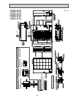
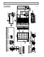
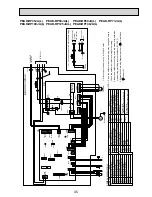
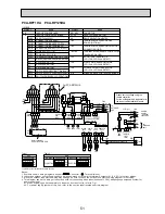
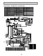
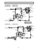
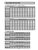
PUHZ-RP100VKA PUHZ-RP125VKA PUHZ-RP140VKA
1 2 3 4 5 6 7 8
1 2 3 4 5 6 7 8
1 2 3 4 5 6 7 8
OFF
ON
100V
MODEL
SW6
*1. MODEL SELECT
*2. SW5 -1 to 5 : Function Switch
SW5-6 *2
OFF
ON
OFF
ON
125V
OFF
ON
OFF
1 2 3 4 5 6
1 2 3 4 5 6
1 2 3 4 5 6
OFF
ON
140V
ON
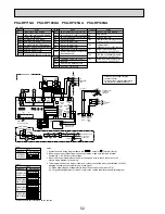
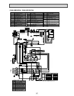
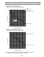
SYMBOL
M-NET ADAPTER
NAME
TB7
CN5
CND
CN2M
SW1
SW11
SW12
LED1
LED2
LED3
LED4
LED5
Terminal Block<M-net connection>
Connector<Transmission>
Connector<Power Supply>
Connector<M-NET communication>
Switch<Status of communication>
Switch<Address setting : 1s digit>
Switch<Address setting : 10s digit>
LED<Power Supply : DC5V>
LED<Connection to Outdoor Unit>
LED<Transmission : Sending>
LED<Transmission : Recelving>
LED<Power Supply : DC12V>
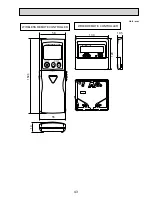
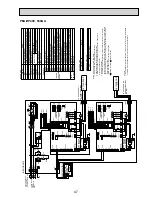
CN5
(WHT)
3
1
LED2
SW1
SW11
SW12
LED3
LED4
TB7
LED1
LED5
2
1
CND
(WHT)
CN2M
(WHT)
M-NET ADAPTER
M-NET
A B S
When M-NET adapter is connected
CNVMNT
(WHT)
3
1
CNDM
(WHT)
CN51
(WHT)
3
1
5
1
CNMNT
(WHT)
CNM
(WHT)
5
1
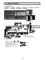
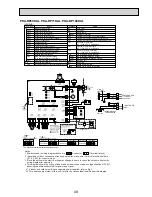
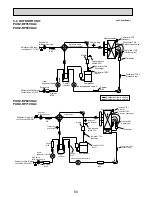
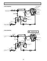
LEV-A
(WHT)
LEV-A
C. B.
LEV-B
(RED)
LEV-B
6
3
5
1
TH7/6
(RED)
63H
(YLW)
TRANS
X51
TH3
(WHT)
CNDC
(PNK)
CNF1
(WHT)
CNF2
(WHT)
TH4
(WHT)
TH7 TH6 TH3 TH4
4
1
2
1
TH33
(YLW)
TH33
3
t°
t°
t°
t°
t°
t°
1
2 1
SW7
SW6
SW1
SW9
CN31
14
1
MF1
MF2
MS
3~
M
M
MS
3~
7
1
CN2
(WHT)
CNS
(WHT)
CNAC
(WHT)
CN4
(WHT)
SS
(WHT)
21S4
(GRN)
2
1
LED1
LED2
X52
F1
F2
F4
F3
*1
*1
2
1
4
3
SW5
SW8
SW4
SWP
21S4
6
1
3
1
7
1
3
1
2
3
1
7
1
7
2
TH32
(BLK)
TH32
2
1
1
3
1
3
CN52C
(RED)
3
3
1
63H
5
3
5
1
5
LEV-C
(BLU)
6
1
LEV-C
RP140 only
M
5
DCL2
IGBT
N2
P2
MS
3~
U
U
V
V
W
W
CN2
(WHT)
CN4
(WHT)
1
7
1
2
2
P. B.
CNDC
(PNK)
BLK
WHT
U
CY1
CY2
LI
NI
EI
E4
E2
E3
U
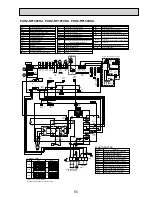
POWER SUPPLY
~/N 230V 50Hz
INDOOR
UNIT
TB1
L
N
S1
S2
S3
MC
3
1
3
1
2
RED
CNAC1
(WHT)
CNAC2
(RED)
1
3
1
3
CN52C
(RED)
52C
52C
BLU
YLW
GRN/YLW
ORN
BRN
RED
WHT
RED
BLK
BLK
BLK
BLK
DCL1
DCL
CB
TB1
MC
MF1, MF2
21S4
63H
TH3, TH33
TH4
TH6
TH7
DCL
Terminal Block<Power Supply, Indoor/Outdoor >
Motor for Compressor
Fan Motor
Solenoid Valve (Four-Way Valve)
High Pressure Switch
Thermistor<Outdoor Pipe>
Thermistor<Discharge>
Thermistor<Outdoor 2-Phase Pipe>
Thermistor<Outdoor>
TH32
Thermistor<Shell>
Electronic Expansion Valve
Reactor
CB
Main Smoothing Capacitor
CY1,CY2
Capacitor
Controller Circuit Board
C.B.
SYMBOL
NAME
SYMBOL
NAME
SYMBOL
NAME
Switch<Function Setup>
Switch<Forced Defrost, Defect History Record
Reset, Refrigerant Address>
Switch<Test Operation>
Switch<Function Switch>
Switch<Model Select>
SW7
SW1
SW4
SW5
SW6
Switch<Function Setup>
SW8
Switch<Pump Down>
SWP
Connector<Emergency Operation>
CN31
LED1, LED2
F1~F4
LED<Operation Inspection Indicators>
CN51
CNM
CNMNT
CNVMNT
CNDM
Connector<A-Control Service Inspection Kit>
Connector
<Connected to Optional M-NET Adapter Board>
Connector
<Connected to Optional M-NET Adapter Board>
Connector
< Connected for Option (Contact Input)>
Fuse
< T6.3AL250V>
X51,X52
Relay
SS
Connector<Connection for Option>
Connector<Connection for Option>
LEV-A, LEV-B, LEV-C
Power Module
N2
Connection Terminal
Connection Terminal<Reactor>
Connection Terminal<Ground>
DCL1,DCL2
IGBT
EI,E2,E3,E4
P.B.
Power Circuit Board
Connection Terminal<U/V/W-Phase>
P2
Connection Terminal
NI
Connection Terminal<N-Phase>
LI
Connection Terminal<L-Phase>
U/V/W
Switch
SW9
The black square (
■
) indicates a switch position.


