17
JEP0-IL9554
Z2
Z1
Y1
a12
a11
Y2
P1
P2
E
AC100/110V
(E
D
)
AC100V
or
DC100V
Y1
Y2
T
E
N
-
+
A
~
V
~
MDG-A3V
Make sure that this circuit is open before test.
DS
kt
※
K
※
※
※
※
※
k
ℓ
ℓ
t
L
ZCT
“
MZT
”
Tripping coil
CB
W
V
U
52a
Phase
meter
MPD-3W
MPD-3C
MPD-3T
(E
D
)
(E
A
)
φ
To
①
To
②
0~1000V
0~1000
Ω
20
Ω
R
2
R
1
From
①
From
②
SW
U
V
u
v
Voltage
regulator
P1 P2
P1, P2 terminal of MDG relay
AC100/110V
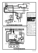
Fig. 2-5 Test method using combinations of the devices
Z2 Z1 P1 P2 Y2 Y1 a11 a12 E
a21
a22
V
A
φ
Y1
Y2
T
E
N
Tripping cord
Voltage cord
Black clip
Red clip
AC100/110V
Current cord
P2
P1
(E
D
)
Remove P1 and P2
Remove the fuses
CB
ZCT
“MZT”
L
K
DS
ℓ
t
kt
VT
※
※
MPD-3C
MPD-3W
MPD-3T
(E
D
)
(E
D
)
(E
A
)
Red clip
Black clip
Black clip
Red clip
Auxiliary power
supply cord
MDG-A3V
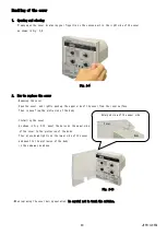
Fig. 2-6 Test method using relay tester
Notes)
These figures show that the V
0
voltage is applied from the
primary side (high-voltage side)
of MPD-3C capacitor simultaneously
in three-phase.
If the V
0
voltage is applied from
the test terminal (T) of MPD-3T,
the voltage value should be one-
tenth of the value from MPD-3C
high-voltage side.
Do not apply voltage into test
terminal (T) more than 380V.
●
If there is no test terminal (kt,
ℓ
t) of ZCT, please pass the red
clip of current cord through ZCT
through hole and connect with the
black clip.
●
For MDG-A3V relay, the
○
+
side
of input polarity is that:
Z1 with I
0
input
Y2 with V
0
input
●
Don't forget to remove the wires
marked by "
※
" in the figures
after the test.
●
If the V
0
voltage is applied from
the test terminal (T) of MPD-3T,
the wires marked by "
※
" in the
figures are not required.
●
Perform the test in combination
with ZCT (MZT type) and ZVT (MPD-
3 type). Otherwise, direct input
to the relay may cause burning
out.


