background image

5.  CONNECTION OF UNIT 

5.6  Connection of Encoder Speed Signal 


I

-16 

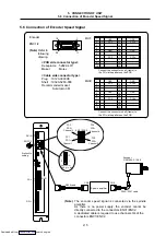
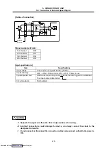
[Outline of connection] 


GND

PC

†

PC

†

1k

Ω

1k

Ω

10

0

Ω

ENC1/2

Spindle
amplifier


[Signal assignment table] 

1st channel 

X00 

2nd channel 

X01 

3rd channel 

X02 

4th channel 

X03 


[Input specifications] 

Item Specifications 

Input voltage 

Line receiver input (X00 to X03)  (5VDC) 

Input sensitivity 

OFF 

 ON  4.5mA or more, ON 

 OFF  1.5mA or less 

Input response time 

X00 to X03 require 50µs or more for the second trigger to be validated.

The input pulse is detected at 


Circuit insulation 

Not insulated 


Separate the signal wire from the drive line/power line when wiring.


Incorrect connections could damage the device, so always connect the cable to the 
designated connector. 


Do not connect or disconnect the connection cables between each unit while the power is 
ON. 


CAUTION


Downloaded from 

ManualsNet.com

 search engine

Содержание MELDAS FCU6-DX561

Страница 1: ...CNC FCU6 DX561 CONNECTION AND MAINTENANCE MANUAL BNP B2302 ENG REMOTE I O UNIT Downloaded from ManualsNet com search engine ...

Страница 2: ...hen the user could be subject to fatalities or serious injuries if handling is mistaken CAUTION When the user could be subject to injuries or when physical damage could occur if handling is mistaken Note that even if the item is ranked as CAUTION serious results could occur depending on the state Always observe the described matters DANGER Not applicable in this manual WARNING 1 Items related to p...

Страница 3: ...Items related to connection Do not apply voltages other than those indicated in this manual on the connector Doing so may lead to destruction or damage Incorrect connections may damage the devices so connect the cables to the specified connectors When using an inductive load such as relays always connect a diode in parallel to the load as a noise measure When using a capacitive load such as a lamp...

Страница 4: ... O Unit I 12 5 4 Connection of RIO Unit I 13 5 5 Connection of Power Supply I 14 5 6 Connection of Encoder Speed Signal I 15 5 7 Connection of Machine Input Output Signal I 17 APPENDIX 1 UNIT OUTLINE DRAWINGS AND INSTALLATION DIMENSIONS I 21 APPENDIX 2 LIST OF CONNECTOR SETS I 22 APPENDIX 3 CABLE MANUFACTURING DRAWING I 23 Appendix 3 1 FCUA R000 Cable Manufacturing Drawing I 25 Appendix 3 2 FCUA R...

Страница 5: ... 2 2 Troubleshooting II 4 2 2 1 Confirmation of trouble state II 4 2 2 2 When in trouble II 5 2 2 3 Behavior of independent faults II 9 3 DAILY MAINTENANCE AND PERIODIC INSPECTION AND MAINTENANCE II 10 3 1 Maintenance Tools II 10 3 2 Replacement Methods II 11 3 2 1 Cable II 11 3 2 2 Unit II 13 Downloaded from ManualsNet com search engine ...

Страница 6: ...I CONNECTION MANUAL Downloaded from ManualsNet com search engine ...

Страница 7: ...manual thoroughly and understand the product s functions and performance before starting use Refer to the following documents for explanations on the functions FX2N Hardware Manual JY992D66301G FX Programming Manual JY992D88101A MELDAS AC Servo Spindle MDS C1 Series Specifications Manual BNP C3000 Refer to the following material for details on EMC Directives for the European CE Marking EMC Install...

Страница 8: ...on panel etc MC link A M60 M600 Series control unit Base I O unit MC link A MC link B Sensor Max 8 channels Synchronous feed encoder Manual pulse generator RS 232C device Servomotor Spindle motor Machine control signal Legend Connections described in this manual Connections described in separate documents MC link B Remote I O unit DX1 M64 BASE T or BASE 5 M65 66 BASE T MC link B Remote I O unit DX...

Страница 9: ...ng terminal Insulation resistance 5MΩ or more with 500VDC megger tester Across entire output terminal batch and grounding terminal General specifications Grounding Class D grounding Use without grounding is possible if grounding is not possible Power voltage 24VDC 10 15 Must be insulated from 100VAC and 200VAC power supply Instantaneous stop tolerance time Operation continues when power instantane...

Страница 10: ...CF31CF32 CF34 CF33 SV2 SV1 H R 3 RIO1 RIO2 DCIN CF10 ENC CR31 SKIP Control unit FCU6 MU MA Main gaounding plate for electric cabinet FG cable FG cable R220 cable R220 cable R220 cable 24VDC 24VDC 24VDC FG cable FCU6 DX3 DX4 HR377 378 Base I O unit 4 ST No P O W E R R U N C P U E STOP RUN R I O E RR 1 E RR 2 Remote I O unit FCU6 DX561 Stabilized power supply DC24V FG 0V Short bar AC input FG cable ...

Страница 11: ...H R 3 RIO1 RIO2 DCIN CF10 ENC CR31 SKIP Grounding plate Grounding plate Grounding plate X X R211 cable R211 cable FG wire FG wire FG wire FG wire X X FCU6 DX3 DX4 HR377 378 Base I O unit Remote I O unit FCU6 DX561 Remote I O unit FCUA DX1 2 Cables which require shield clamp with connector cases The shield of encoder cable R000 for the speed signal input must be clamped with the connector case Shie...

Страница 12: ...s I 6 3 2 3 Connecting Spark Killers Connect a spark killer on the coil or contact in parallel for noise countermeasures Use spark killers which are 0 033 to 0 1µF 10 to 120Ω Coil Contact E SK SK Downloaded from ManualsNet com search engine ...

Страница 13: ... S U B I S HI M D S B S V J2 4 ST No POW ER RU N CPU E S T O P RU N RI O ERR 1 ERR 2 Remote I O unit FCU6 DX561 Remote I O unit FCUA DX1 100mm or more heat dissipation allowance 50mm or more heat dissipation allowance 50mm or more 10mm or more 10mm or more 10mm or more 15mm or more wiring allowance 15mm or more wiring allowance 150mm or more heat dissipation wiringallowance 100mm or more heat diss...

Страница 14: ...packing Oil will easily accumulate at the ceiling and can enter the cabinet from the screw holes Always take special measures such as using oil preventing packing Fitting Packing Cable Cable inlet Example 2 Avoid machining in the area after installing each unit Cutting chips etc could get on the electronic parts and cause damage 3 Design so that the cabinet s internal temperature rise is 10 C or l...

Страница 15: ...e I O unit DX1 Communication terminal MC link B terminator R TM MDS B CVE To next remote I O unit Ethernet communication device 3 phase 200VAC to 230VAC No fuse breaker NFB OT release switch Insert when required X axis and Y axis Spindle AC servomotor with detector HC153TA33 Spindle motor SJ V15 02 R056 cable 7 5kW rating 30 min Regenerative resistor CNV2 CNV12 cable Terminator MDS A TM AC reactor...

Страница 16: ...ignal input connector 8 Digital signal input connector 9 Digital signal output connector 10 Remote I O connection connector 11 Remote I O connection connector Note The encoder speed signal is connected via the spindle amplifier As there is no power supply the encoder cannot be directly connected to the connectors ENC1 ENC2 Front view ENC1 2 ST No 4 DO L 9 DI L 7 0 1 2 3 4 5 6 7 8 9 A B C D E F ST ...

Страница 17: ...e I O unit FCU6 DX561 Name Explanation RIO1 This is connected to the base I O unit RIO2 This is used to connect the terminator or to expand the remote I O unit The remote I O unit can be expanded by up to four stations ENC1 Connected with encoder via spindle amplifier ENC2 Connected with encoder via spindle amplifier DI L DI 28 Sink Source DI R DI 16 Sink Source DO L DO 32 Source ST No Set the sta...

Страница 18: ... ALM NC RST NC SYS NC LED WD ER ENC2 CBUS 1 ENC1 SV2 SV1 0 0 SKIP H AN DL C H 1 C H 3 R S2 32C C H1 CH2 未 使 用 未 使 用 未 使 用 FG カ ー ト ゙ ア ト ゙オ ン 用 取 付 け 穴 L G CF31 CF32 CF33 CF34 RIO1 RIO2 DCIN CF10 CF11 4 S T No P O W E R R U N C P U E S T O P R U N R I O ER R1 ER R2 Front Back Bottom view Remote I O unit FCU6 DX561 CF11 CF10 R211 cable F010 cable F050 cable RIO1 RIO2 DCIN RIO1 RIO2 X R211 cable R21...

Страница 19: ...s for details Example for expanding remote I O units Terminator R TM X R211 cable R211 cable RIO2 RIO2 RIO2 RIO1 RIO1 X X Front Back Bottom view RIO1 RIO2 DCIN RIO2 RIO1 DCIN RIO2 RIO1 RIO1 RIO2 RIO1 RIO2 X X Front Back Bottom view Front Back Bottom view Front Back Bottom view Remote I O unit FCU6 DX561 Remote I O unit FCU6 DX561 Remote I O unit FCUA DX1 Remote I O unit FCUA DX1 Remote I O unit FC...

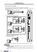
Страница 20: ...I L DI R 24VDC FG 0V DI L 24V B4 B3 A4 A3 24V B4 B3 A4 A3 For sink input For source input 3 DO L power connection for DO circuit Fixed to source output 24VDC FG 0V DO L 24V B4 B3 A4 A3 Note Connect the power or GND to all of the common pins on the DI L R and DO L connector Incorrect connections could damage the device so always connect the cable to the designated connector Do not connect or discon...

Страница 21: ...C1 GND PC3 GND PC2 GND PC4 1 2 3 4 5 6 7 8 9 10 11 12 13 14 15 16 17 18 19 20 I I I I GND PC2 GND PC4 ENC1 ENC2 Connect the connector shell frame to the FG via the pattern on the PCB Connect the connector shell frame to the FG via the pattern on the PCB PCB side connector type Receptacle 52822 4011 Maker Molex Cable side connector type Plug 10120 3000VE Shell 10320 52F0 008 Recommended maker Sumit...

Страница 22: ...sensitivity OFF ON 4 5mA or more ON OFF 1 5mA or less Input response time X00 to X03 require 50µs or more for the second trigger to be validated The input pulse is detected at Circuit insulation Not insulated Separate the signal wire from the drive line power line when wiring Incorrect connections could damage the device so always connect the cable to the designated connector Do not connect or dis...

Страница 23: ...G B4 A4 Control circuit RA PL B3 DO_COM A3 DO_24V DO_0V B4 A4 Output circuit sink type DI L R DO L Machine control panel B3 Input circuit A3 Control circuit Output circuit RA PL source type source type RIO1 RIO2 1 2 Stabilized power supply DCIN 3 0V 24VDC FG B3 DO_COM A3 DO_24V DO_0V DI_0V DI_24V DI_COM B4 A4 B4 A4 3 3kΩ 4 points X04 to X07 4 3kΩ 40 points X10 to X57 DI L R DO L Machine control pa...

Страница 24: ...de control panel etc 0V 24VDC PL RA X Y00 Y01 Y02 Y03 Y04 Y05 Y06 Y07 Y10 Y11 Y12 Y13 Y14 Y15 Y16 Y17 DO_COM DO_COM Y20 Y21 Y22 Y23 Y24 Y25 Y26 Y27 Y30 Y31 Y32 Y33 Y34 Y35 Y36 Y37 DO_COM DO_COM 2 1 3 LG 24VDC 1 2 3 FG 0V 1 2 3 LG TXRX TXRX TXRX TXRX X40 X41 X42 X43 X44 X45 X46 X47 X50 X51 X52 X53 X54 X55 X56 X57 DI_COM2 DI_COM2 Remote I O unit Base I O unit Adaptive connector DCIN RIO1 RIO2 RI L D...

Страница 25: ...ON OFF 1 5mA or less OFF ON Approx 4ms ON OFF Approx 4ms General input X20 to X57 X00 to X17 are incorporated in the digital filter Can be changed to 0 to 60ms note that the minimum is 50µs Note Input response time X00 to X03 require 50µs or more for the second trigger to be validated The input pulse is detected at Circuit insulation Photo coupler insulation Excluding line receiver input Note The ...

Страница 26: ...r insulation Caution When using an inductive load such as a relay always connect a diode voltage resistance 100V or more 100mA or more in reverse direction in parallel to the load Note that the device will be damaged if the diode orientation is incorrect When using a capacity load such as a lamp always connect a protective resistor R 150Ω serially to the load to suppress rush currents Make sure th...

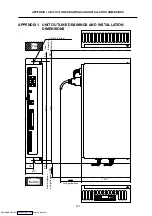
Страница 27: ...ENSIONS 0 1 2 3 4 5 6 7 8 9 A B C D E F ST No P O W E R R U N C P U E ST OP RUN PROG PORT D I R D I L D O L RIO ERR1 ERR2 ENC1 ENC2 DC IN Wiring allowance 2 M5x0 8 screw 80 180 60 30 Heat dissipation wiring allowance Heat dissipation allowance Top 10 50 360 10 100 380 Bottom Downloaded from ManualsNet com search engine ...

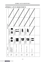
Страница 28: ...ector 3M 10120 3000VE 2 pcs Connector 3M 7940 6500SC 4 pcs Connector Tyco Electronics AMP 1 178288 3 1 pc Connector Tyco Electronics AMP 2 178288 3 1 pc Connector 3M 7940 6500SC 2 pcs Application Remote I O unit FCU6 DX561 Spindle amplifier MDS B C1 SP MDS B SPJ2 DIO connector terminal block I O communication connector 24VDC power connector DIO connector Type FCUA CS000 FCUA CS301 FCUA CN211 FCUA ...

Страница 29: ...n Wire Solder 3 Lightly press down one side of the wire barrel using radio pliers Wire barrel This is a barrier to prevent incorrect insertion Do not bend Radio pliers 5 Firmly press down the sheath retainer in the same manner as the wire barrel Sheath retainer 7 Lastly insert the soldered contact with wire into the housing Pay attention to the insertion direction 2 Insert the wire into the contac...

Страница 30: ...unit and the cable length L3 from this unit to each unit must be less than this value R211 Control unit Base I O unit Maximum cable length RIO1 ENC1 ENC2 F010 Servo amplifier Remote I O unit Encoder L2 L1 R300 F301 F050 Expansion I O unit RIO1 RIO2 L3 R211 R000 Remote I O unit FCU6 DX561 DI L R DO L Machine operation panel Note 2 Symbols for writing cable drawings The following symbols are used in...

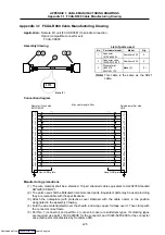
Страница 31: ...rts used shall be Mitsubishi recommended parts Equivalent parts may be used providing they are compatible with the specifications 3 Attach the nameplate with protective cover stamped with the cable name in the position designated in the assembly drawing 4 Fold the wire material shield over the sheath and wrap copper foil tape over it Then clamp with the connector case frame 5 Part No 1 connector a...

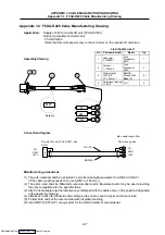
Страница 32: ...ing they are compatible with the specifications 3 Attach the nameplate with protective cover stamped with the cable name in the position designated in the assembly drawing 4 Install each crimp terminal side after stamping the name of each signal on the mark tube 5 Protect both ends of the wire material with insulation bushing 6 Use AWG18 0 75mm2 or equivalent for the shield treatment wire material...

Страница 33: ...exceeds 10m use AWG16 1 25mm2 2 The parts used shall be Mitsubishi recommended parts Equivalent parts may be used providing they are compatible with the specifications 3 Attach the nameplate with protective cover stamped with the cable name in the position designated in the assembly drawing 4 Install each crimp terminal side after stamping the name of each signal on the mark tube 5 Protect both en...

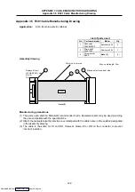
Страница 34: ...s used shall be Mitsubishi recommended parts Equivalent parts may be used providing they are compatible with the specifications 2 Attach the nameplate with protective cover stamped with the cable name in the position designated in the assembly drawing 3 The cable is the same for DI and DO However stamp DI or DO on the connector to prevent incorrect insertion List of parts used No Part name model M...

Страница 35: ...tsubishi recommended parts Equivalent parts may be used providing they are compatible with the specifications 2 Attach the nameplate with protective cover stamped with the cable name in the position designated in the assembly drawing 3 The cable is the same for DI and DO However stamp DI or DO on the connector to prevent incorrect insertion List of parts used No Part name model Maker Qty 1 Connect...

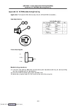
Страница 36: ...X 100Ω Manufacturing precautions 1 The parts used shall be Mitsubishi recommended parts Equivalent parts may be used providing they are compatible with the specifications 2 Cover the 100Ω terminator with a black insulation tube 3 Stamp the connector name R TM in white on the rear of the connector List of parts used No Part name model Maker Qty 1 Connector 1 178288 3 X type Tyco Electronics AMP 1 2...

Страница 37: ... unit for supplying 24VDC is a UL approved part Use a UL approved part for the power supply unit supplying 24VDC to this unit 2 Unit ambient temperature The remote I O unit FCU6 DX561 complies with UL Standards on the condition that it is used within the maximum ambient temperature given in 3 1 General Specifications in Chapter 3 of this manual Design so that the maximum ambient temperature of thi...

Страница 38: ...II MAINTENANCE MANUAL Downloaded from ManualsNet com search engine ...

Страница 39: ...X2N Series and has two remote I O controllers mounted This functions as the remote I O s slave station CPU System control BPU G A PLC operation IO G A External I O interface Memory EEPROM For ladder storage SRAM Memory for execution RIO G A Remote I O controller Occupies two stations I O interface ENC1 2 connector Encoder speed signal connection 4ch DI L R connector Input 44 points DO L connector ...

Страница 40: ... rotary switch Set an even number 8 and following Loop back test mode for testing If the base I O occupies 0 and 1 set the switch to 2 Explanation of LEDs POWER Green 5V power output This turns ON when the state is normal display RUN Green Operation display When the unit power is turned ON the self diagnosis function activates If there is no error the operation state is entered RUN LED turns ON CP...

Страница 41: ...error Correspondence for error POWER 5VDC output display Green Lit Not lit 24VDC 10 15 Check the input RUN Operation display Green Lit Not lit Check the RUN STOP slide switch setting CPU E CPU error display Red Not lit Lit Refer to section 2 2 2 RIOERR1 Onboard I O 1st station communication alarm Red Not lit Lit RIOERR 2 Onboard I O 2nd station communication alarm Red Not lit Lit Check the station...

Страница 42: ...the operation of another machine there may be an error in the power voltage or the trouble may be caused by noise etc Check whether the power voltage is normal does it drop momentarily when other machines are operating and whether noise measures have been taken Does the trouble occur during a specific mode Does the trouble occur when the overhead crane is operating What is the frequency in the sam...

Страница 43: ...r does not turn ON The external power turns ON but the control power does not turn ON The power turns OFF The communication alarm display RIOERR1 RIOERR2 LED turns ON The 5VDC output display POWER LED turns OFF The CPU error display CPU E turns ON flickers The operation display RUN LED does not turn ON The load does not turn ON OFF even though the corresponding output is turned ON or OFF in the la...

Страница 44: ...wer turns ON but the NC control power does not turn ON Cause Remedy The external power supply output is not correct Disconnect the cable between the unit and the external power supply and check that the external power supply output voltage is normal The power cable is disconnected or broken Check the cable between the unit and external power supply and securely insert it Check that the cable is no...

Страница 45: ...dropped for an instant If the power is supplied correctly contact the Service Center The CPU error display CPU E turns ON flickers Cause Remedy If the CPU does not run properly because inductive foreign matter has entered or because of abnormal noise from an external source or if the operation cycle exceeds 200ms the watch dog timer error will occur and cause this LED to turn ON If the watch dog t...

Страница 46: ... etc or a contact fault has occurred due to a rough contact surface If the error occurs even after the relay is replaced or the cause of the relay output contact fusion is removed contact the Service Center A fault has occurred in the FX2N 80BMT NC card output circuit Check whether there are any causes of overcurrent such as a load short circuit Measure the output voltage with a tester If the spec...

Страница 47: ...r The 24VDC power for control turned OFF failed The power cable was disconnected broken The PLC will stop The DO output will turn OFF The 24VDC power for DO turned OFF failed The DO output will turn OFF The remote I O cable was disconnected broken The remote I O cable is affected by noise The RIO communication will stop The communication alarm display RIOERR1 or RIOERR2 LED will turn ON The contac...

Страница 48: ... ON AC voltmeter Measure the AC power voltage The tolerable error is 2 or less To measures the AC power voltage being supplied to the external 24VDC power supply unit DC voltmeter Max scale 30V The tolerable error is 2 or less To measure the DC power voltage External power supply 24V control section machine input output interface Phase rotation meter To check the connection order of the AC 3 phase...

Страница 49: ...uld be imposed Disconnect each cable with the following procedures a For the following type of connector press the tabs with a thumb and forefinger in the direction of the arrow and pull the connector off 1 Press 2 Pull Y 1 Press 2 Pull 1 Press 2 Pull Do not connect or disconnect the connection cables between each unit while the power is ON Do not connect the cable by pulling on the cable wire CAU...

Страница 50: ... the connector off 1 Open 2 Pull c For a flat cable type connector without claws hold the connector with a thumb and forefinger and pull the connector off 2 Pull 1 Hold with thumb and forefinger Do not connect or disconnect the connection cables between each unit while the power is ON Do not connect the cable by pulling on the cable wire CAUTION Downloaded from ManualsNet com search engine ...
Страница 51: ...it and fix the unit with the fixing screw at the original position 6 Reconnect the connected cables at the original positions Connect the cables to the predetermined connectors 7 Check that all cables have been connected correctly and then close the electric cabinet door Electric cabinet PLC unit Fixing screw two screws Lift up Screw B Screw A CAUTION Incorrect connections may damage the devices s...

Страница 52: ...Revision history Revision Date of revision Revision details 00 12 01 First edition issued Downloaded from ManualsNet com search engine ...

Страница 53: ...fications subject to change without notice Printed in Japan on recycled paper MITSUBISHI ELECTRIC CORPORATION HEAD OFFICE MITSUBISHI DENKI BLDG 2 2 3 MARUNOUCHI CHIYODA KU TOKYO 100 8310 JAPAN MODEL Manual No MODEL CODE Downloaded from ManualsNet com search engine ...
Отзывы: