190
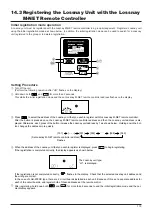
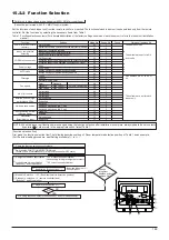
[Procedure] (Set only when change is necessary.)
Check the set contents of each mode. When the set contents of a mode were changed by function selection, the functions of that mode also change.
Check the set contents as described in steps
to
and change the setting based on the entries in the Table 1 check field. For the factory settings, refer to the indoor unit installation manual.
* If the remote controller enters the OFF state after the “FUNCTION” and room temperature displays “
” have flashes for two seconds, communica-
tion is probably abnormal. Make sure there are no noise sources near the transmission line.
NOTE: If you make a mistake during operation, end function selection by step
and repeat selection from step
.
* When setting mode 1 to 3, set the unit address No. to “00”.
* When setting modes 7 to 11:
- When setting for each indoor unit, set the unit address No. to “01-04”.
- When batch setting for all indoor units, set the unit address No. to “AL”.
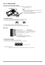
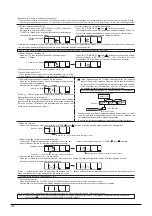
Set the remote controller to Off.
Press and hold down the
[FILTER] and
[TEST] buttons at
the same time for two seconds or longer.
“FUNCTION” blinks for a while, then the remote controller display
changes to the display shown below.
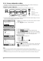
Set the outdoor unit refrigerant address No.
When the
[TIMER SET (
) and (
)] buttons are pressed,
the refrigerant address No. decreases and increases between 00 and 15.
Set it to the refrigerant address No. whose function you want to select.
(This step is unnecessary for single refrigerant system.)
FUNCTION
FUNCTION
Refrigerant address
display
Set the indoor unit address No.
Press the
[Timer selection] button. The unit address No.
display “– –” flashes.
When the
[TIMER SET (
) and (
)] buttons are pressed, the unit ad-
dress No. changes in 00
01
02 03
04
AL order. Set it to the
unit address No. of the indoor unit whose functions you want to set.
FUNCTION
FUNCTION
Unit address No. display
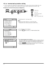
Refrigerant address and unit address No. registration
Press the
[Mode selection] button. The refrigerant address and
unit address No. are registered.
After a while, the mode No. display “– –” flashes.
* When “
” flashes at the room temperature display, the selected re-
frigerant address is not in the system.
When “F” is displayed at the unit address No. display, and when it flashes
together with the refrigerant address display, the selected unit address
No. does not exist. Correctly set the refrigerant address and unit ad-
dress No. by repeating steps
and
.
FUNCTION
Mode No. display
When registered using the
[Mode selection] button, the registered
indoor unit begins fan operation. When you want to know the location of
the indoor units of the unit address No. whose functions were selected,
check here. When the unit address No. is 00 or AL, all the indoor units of
the selected refrigerant address perform the fan operation.
Ex) When refrigerant address 00, unit address No. = 02 registered
* When grouping by different refrigerant systems and an indoor unit other
than the specified refrigerant address performs the fan operation, the
refrigerant address set here is probably duplicated.
Recheck the refrigerant address at the outdoor unit rotary switches.
Outdoor unit
Indoor unit
Refrigerant address 00
Unit address
No. 01
Fan operation
Registration
Unit address
No. 02
Unit address
No. 03
Remote Controller
Mode No. selection
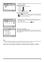
Select the mode No. you want to set with the
[TEMP. (
) and (
)] buttons. (Only the settable mode numbers can be selected.)
Select the setting contents of the selected mode.
When the
[Timer selection] button is pressed, the current set-
ting No. flashes. Use this to check the currently set contents.
The contents set at steps
to
are registered.
When the
[Mode selection] button is pressed, the mode No. and setting No. flash and registration begins. The flashing mode No. and
setting No. change to a steady light and setting ends.
* When “– –” appears at the mode No. and setting No. displays and “
” flashes at the room temperature display, communication is probably abnormal.
Make sure there are no noise sources near the transmission line.
To select more functions, repeat steps
to
.
End function selection.
Press and hold down the
[FILTER] and
[TEST] buttons at the same time for two seconds or longer.
After a while, the function selection display disappears and the remote controller returns to the air conditioner off display.
* Do not operate the air conditioner from the remote controller for 30 seconds after the end of function selection.
NOTE: When the functions of an indoor unit were changed by function selection after the end of installation, always indicate the set contents
by entering a
or other mark in the appropriate check field of Table 1.
FUNCTION
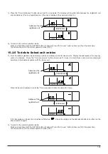
Mode No. 02 = Room temperature detection position
Select the setting No. using the
[TEMP. (
) and (
)] buttons.
Setting No. display
FUNCTION
FUNCTION
Setting No. 1 = Simultaneous operation indoor units balance
Setting No. 3 = Remote controller built-in sensor
FUNCTION
FUNCTION
Mode No. display
1
2
0
2
4
5
6
7
8
9
0
3
8
3
7
2
3
3
2
7
A
D
E
F
G
E
A
B
F
E
C
B
C
Содержание Lossnay PZ-41SLB-E
Страница 4: ...CHAPTER 1 Ventilation for Healthy Living Lossnay Unit ...
Страница 17: ......
Страница 18: ...CHAPTER 2 Lossnay Construction and Principle ...
Страница 24: ...CHAPTER 3 General Technical Considerations ...
Страница 41: ......
Страница 42: ...CHAPTER 4 Characteristics ...
Страница 56: ...53 CHAPTER 4 Characteristics ...
Страница 57: ...54 CHAPTER 4 Characteristics ...
Страница 59: ......
Страница 60: ...CHAPTER 5 System Design Recommendations ...
Страница 68: ...CHAPTER 6 Examples of Lossnay Applications ...
Страница 83: ......
Страница 84: ...CHAPTER 7 Installation Considerations ...
Страница 88: ...CHAPTER 8 Filtering for Freshness ...
Страница 96: ...CHAPTER 9 Service Life and Maintenance ...
Страница 98: ...CHAPTER 10 Ventilation Standards in Each Country ...
Страница 101: ......
Страница 102: ...CHAPTER 11 Lossnay Q and A ...
Страница 108: ...Lossnay Remote Controller ...
Страница 109: ......
Страница 197: ...MEMO ...
Страница 198: ...Y04 002 Jul 2004 MEE ...

