background image

4 - 7                                                                                                                                                       4 - 7

MELSOFT

4   CREATING THE SECOND SCREEN

4.4.2 Setting level display function

Describes the operations for setting the level display function.
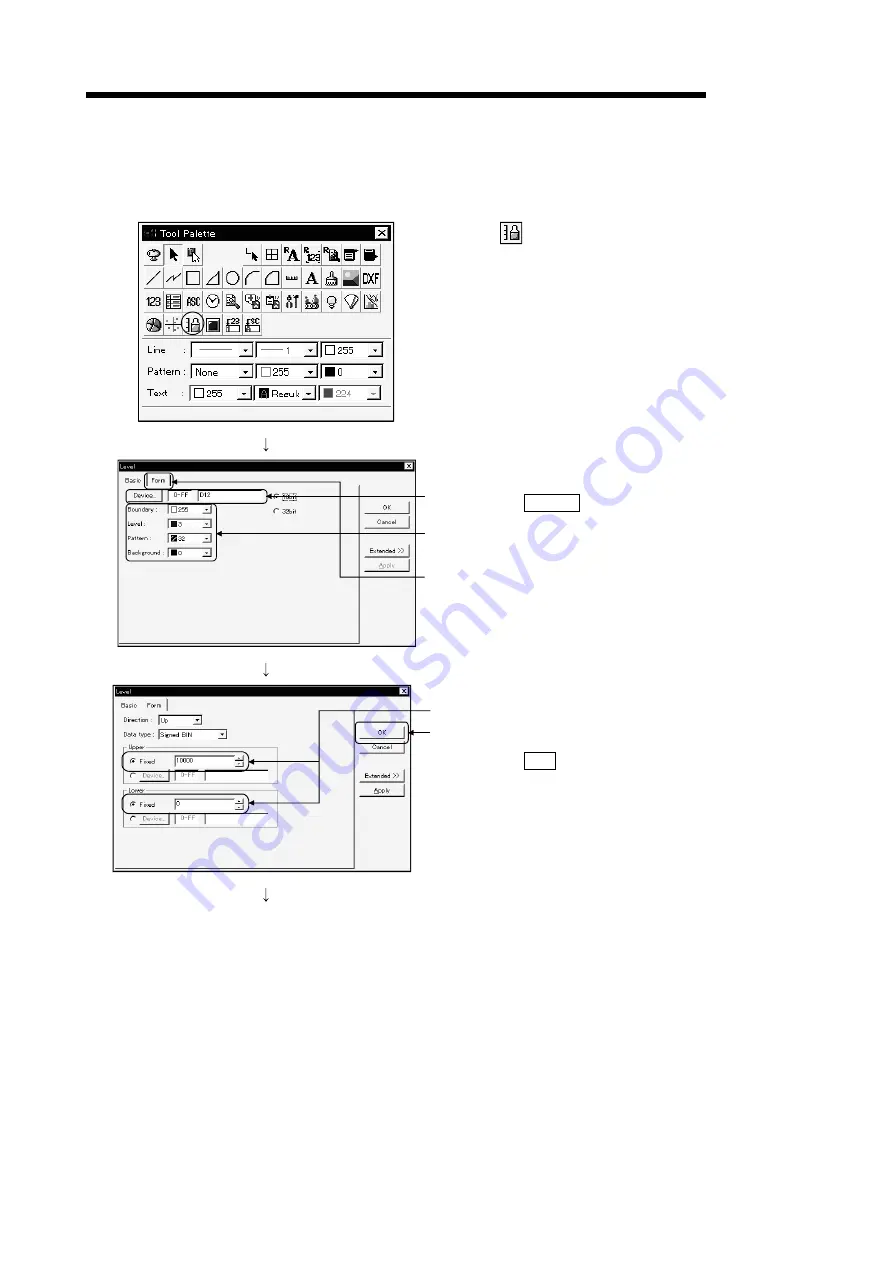
1) Click 

 on the tool pallet.

3)

4)

5)

2) The dialog box appears.

3) Click the  Device  button to designate the device.

Device: Set to D12.

4) Set the attributes of the level display as shown on

the left.

5) Click the [Form] tab.

6)

7)

6) Set the Fixed value of the Upper value to "10000"

and that of the Lower value to "0".
(You can type them directly from the keyboard.)

7) Click the  OK  button.

(To the following page)

Содержание GOT 900

Страница 1: ...GOT Series Human Machine Interface Operating Manual Introductory GOT900 INDUSTRIAL AUTOMATION MITSUBISHI ELECTRIC MITSUBISHI ELECTRIC Art Nr 136208 01 08 2000 SH 080116 A ...

Страница 2: ...ve this manual to make it accessible when required and always forward it to the end user Design Precautions WARNING Some failures of the GOT main unit communication board or cable may keep the outputs on or off An external monitoring circuit should be provided to check for output signals which may lead to a serious accident Not doing so can cause an accident due to false output or malfunction If a...

Страница 3: ...OT user s manual Not doing so can cause an electric shock fire malfunction or product damage or deterioration When mounting the GOT main unit to an enclosure tighten the mounting screws in the specified torque range Undertightening can cause a drop short circuit or malfunction Overtightening can cause a drop short circuit or malfunction due to the damage of the screws or module When loading the co...

Страница 4: ...h as chips and wire offcuts entering the module Not doing so can cause a fire failure or malfunction Plug the bus connection cable by inserting it into the connector of the connected module until it clicks After plugging check that it has been inserted snugly Not doing so can cause a malfunction due to a contact fault Plug the communication cable into the connector of the connected module and tigh...

Страница 5: ...fy the module Doing so can cause a failure malfunction injury or fire Do not touch the conductive and electronic parts of the module directly Doing so can cause a module malfunction or failure The cables connected to the module must be run in ducts or clamped Not doing so can cause the module or cable to be damaged due to the dangling motion or accidental pulling of the cables or can cause a malfu...

Страница 6: ...rsion SH 080111 A This manual confers no industrial property rights or any rights of any other kind nor does it confer any patent licenses Mitsubishi Electric Corporation cannot be held responsible for any problems involving industrial property rights which may occur as a result of using the contents noted in this manual 2000 MITSUBISHI ELECTRIC CORPORATION ...

Страница 7: ...3 15 3 1 Creating a Screen like This 3 1 3 2 Common Setting before Drawing 3 2 3 2 1 Selecting GOT PLC type 3 2 3 2 2 Setting screen switching device 3 3 3 3 Creating the First Screen 3 4 3 4 Setting Objects 3 5 3 4 1 Setting numerical display function 3 5 3 4 2 Setting numerical input function 3 7 3 4 3 Setting lamp display function 3 8 3 4 4 Setting touch key function 3 11 CHAPTER4 CREATING THE ...

Страница 8: ...1 to 5 6 5 1 Connecting the Personal Computer and GOT 5 1 5 2 Installing the OS 5 1 5 3 Downloading Screen Data 5 2 5 4 Connecting to PLC CPU 5 3 5 5 Executing Monitoring 5 4 5 6 Upload 5 5 5 7 Sequence Program Used in the Manual 5 6 INDEX Index 1 ...

Страница 9: ...n5 compatible Connection System Manual Gives the specifications system configuration setting method and connection diagram of each connection form available for the GOT A900 series Available as option SH 080119 13JR20 A985GOT A975GOT A970GOT A960GOT User s Manual Explains the specifications general system configuration component devices part names option unit loading methods installation and wirin...

Страница 10: ...56GOT A953GOT A951GOT A951GOT Q A950GOT and A950 handy GOT Communica tion board Bus connection board Generic term of A9GT QBUSS A9GT QBUS2S A9GT BUSS and A9GT BUS2S GT Works Version5 SW5D5C GTWORKS E software package GT Designer Version5 Generic term of SW5D5C GOTR PACKE software package and SW5D5C GOTR PACKEV software package GT Designer Abbreviation of image creation software GT Designer for GOT...

Страница 11: ...dication data display message display and other operations which were previously performed on an operator panel Space saving Cost reduction 2 About monitor screen data to be displayed on the GOT The monitor screen data to be displayed on the GOT are created on a personal computer using the dedicated software GT Designer You can perform the corresponding functions of the GOT by pasting display fram...

Страница 12: ...ecimal Touch key setting Bit momentary Write device M0 Touch key setting Bit momentary Write device M1 Lamp display setting Bit Read device Y10 2 Operation explanation Data 0 GOT PLC CPU M0 Y10 Y10 M1 Y10 Turns ON Touch Run Stop Run lamp K123 MOV D10 1 While the Run touch key of the GOT is touched the bit device M0 is ON Run Run lamp Stop Data 0 GOT PLC CPU M0 Y10 Y10 M1 Y10 Turns ON Turns ON K123...

Страница 13: ...uched the bit device M1 of the PLC CPU is ON Since the bit device Y10 of the PLC CPU turns OFF the lamp display of the GOT turns OFF 1 3 Mouse Usage and Operations Describes basic operations of the mouse 1 Click Click Press the left button of the mouse once then release without moving the mouse This is the most common operation Using the right button to perform this operation is called right click...

Страница 14: ...tall the GT Designer Start the GT Designer GT Works Version5 GT Designer Version5 Operating Manual Start up Manual Carry out common setting Refer to 3 1 Prepare the user screen data Connect the GOT and the personal computer with RS 232C and turn ON the GOT Using the GOT for the first time Install the OS and the communication driver Transfer the user screen data End Connect to the PLC and start mon...

Страница 15: ...signer Version5 Reference Manual Click when drawing a rectangle Click when drawing a scale Click when entering a text 1 When drawing a rectangle 1 2 3 1 Click the left mouse button at the start point of the rectangle 2 Drag the cursor to the end point 3 Release the left mouse button A rectangle appears 2 When drawing a scale 1 As the scale setting dialog box appears make settings Scale points Set ...

Страница 16: ...igure to enlarge 2 Press the left mouse button at the handle of the selected figure or object in the direction to enlarge then drag it 3 Release the left mouse button The figure or object is resized Holding down the Shift key and changing the size resizes the figure at equal ratios Holding down the Ctrl key and changing the size resizes the figure relative to the center 2 Copying a figure or objec...

Страница 17: ...CREATING SCREENS CHAPTER3 CREATING SCREENS 3 1 Creating a Screen like This In this chapter a screen as shown below is created Numerical display function Numerical input function Lamp display function Touch key function 3 ...

Страница 18: ...f the GOT and the PLC to use 1 Starting GT Designer displays the project selection dialog box Click New 3 2 The dialog box appears 3 Click the list box and set the type of the GOT and the PLC Here set as follows GOT type A97 GOT 640 480 PLC type MELSEC A 4 4 Click the OK button The GOT PLC types are set POINT The GOT PLC type setting dialog box is also displayed by choosing the Common GOT PLC Type...

Страница 19: ... screen is set to D999 because only the base screens are switched in the manual 1 Click the Common Switching Screen menu 3 2 The dialog box appears 3 Click the Device button on the base screen to set the screen switching device of the base screen 5 6 7 4 The dialog box appears 5 Click the list box to set to D 6 Click button 9 three times 7 After setting is completed click the OK button To the foll...

Страница 20: ...tching devices must be used only as such Word devices D or W are mainly used as the screen switching device but device GD for the GOT is also available Device GD Device GD is a word device of the GOT In device GD 1024 points from GD0 to GD1023 are available There is a bit device GB in which 1024 points from GB0 to GB1023 are also available 3 3 Creating the First Screen Refer to Chapter 2 and creat...

Страница 21: ...ns for setting numerical display function 1 Click on the tool palette 3 4 2 The dialog box appears 3 Click the Device button and set the device Device Set to D12 4 Check the check box and click the Shape button to designate the background figure 5 6 5 The dialog box appears Click the figure to be used as the background Here select figure 21 6 Click the OK button To the following page ...

Страница 22: ...display range appears at the upper left of the screen Move the frame to the desired position and click Change the size of the outer figure or the inner object frame with the handle Refer to 2 2 10 Copy the numerical display function and double click the copied numerical display function 11 Change the device to D13 and click the OK button 12 This sets two numerical display functions ...

Страница 23: ...e Here set as shown on the left 4 After setting click the OK button and place the display range frame of the numerical input function 5 Copy the numerical input function and change the device of the second numerical input function to D11 6 This sets two numerical input functions POINT In this manual make setting to display the key window as soon as you touch the part where the numerical input obje...

Страница 24: ...ribes the operations for setting the lamp display function 1 Click the List button on the template parts display area 2 The template directory tree is displayed Click the button of the parts library folder 3 As the library names appear double click Lamp 1 To the following page ...

Страница 25: ...rt display area Here use No 1 6 Move the cursor to the screen A frame of display range appears Move the frame to the desired position and click 7 Double click the pasted lamp 9 10 8 The dialog box appears 9 Click the Device button and set the device Device Set to Y0 10 After setting the device click the Case Bit tab 11 Click the Text button To the following page ...

Страница 26: ...k the Copy from ON button 14 Set the attributes of the lamp Here designate as shown on the left 15 Click the OK button 16 The lamp set on the screen is updated 17 Repeat steps 7 to 16 for the number of lamps to set Here repeat 3 times Device Set Y1 to Y3 Text Type Y1 to Y3 The lamp pasted in 7 must be copied and pasted to a new position Refer to 2 2 POINT With the Edit Consecutive Copy menu a figu...

Страница 27: ...nly Refer to Section 3 4 3 for the way to display Template directory tree 2 Parts in the library are displayed on the template part display area 3 Click a lamp on the template part display area Here use No 16 4 Move the cursor to the screen A frame of display range appears Move the frame to the desired position and click 5 Double click the pasted touch key To the following page ...

Страница 28: ...T 3 CREATING SCREENS From the previous page 6 7 6 As the dialog box appears make the following settings Display trigger Choose Bit Device Set to M70 7 Click the Case tab 8 Click the ON Text button To the following page ...

Страница 29: ... setting each item click the OK button Position Choose Bottom Text Type M70 Horizontal alignment Click the center button 10 11 12 10 Click the Copy from ON button 11 Set the attributes of the touch key and text Here designate as shown on the left 12 Click the Action tab To the following page ...

Страница 30: ...T 3 CREATING SCREENS From the previous page 13 Click the Bit button 14 15 16 14 The dialog box appears Select Alternate 15 Click the Device button and set the device to M70 16 Click the OK button To the following page ...

Страница 31: ... the screen is updated 19 Repeat steps 5 to 18 for the number of touch keys to set Here repeat 3 times Device Set M71 to M73 Text Type M71 to M73 The key pasted before step 5 must be copied and pasted to a new position Refer to 2 2 POINT With the Edit Continuous Copy menu a figure can be copied continuously ...

Страница 32: ...t screen The switching button to the second screen is added to the first screen 1 Adding the screen switching button to the first screen The screen switching button to the second screen must be set on the first screen Set a touch key at the lower right corner of the first screen Touch key function 2 Creating the second screen Touch key function Level display function Alarm list display function Pa...

Страница 33: ... operations for creating the second screen 1 Click on tool bar 1 2 3 2 Click the spin box and set the screen number to 2 3 Click the OK button The second screen is created First create a screen as follows by referring to Chapter 2 Use rectangles to create these Use scales to create these 4 ...

Страница 34: ...limit switch operated Check the product 3 Y2 Product limit switch does not operate Check for presence absence of the product 4 Y3 Hydraulic pressure of finishing machine 1 is low Supply hydraulic oil 1 Click the Draw Comment menu 2 3 2 As the dialog box appears type a comment from the keyboard 3 After comment creation click the Enter button to register the No 1 comment 4 5 4 Create remaining No 2 ...

Страница 35: ...ter 4 4 1 Setting touch key function for screen switching Describes the operations for setting the touch key function for screen switching 1 Paste to the screen the No 15 key of Switch 1 registered on Template 2 Double click the pasted key 3 The dialog box appears Click the Case tab 4 Click the ON Text button To the following page ...

Страница 36: ...K button Position Select Center Text Input Screen 1 Horizontal alignment Click the center button Vertical alignment Click the center button 6 7 8 6 Click the Copy from ON button 7 Set the attributes of the touch key and text Here designate as shown on the left 8 Click the Action tab 9 Click the Base button To the following page ...

Страница 37: ...creen 1 for the touch key set on the second screen 12 Click the OK button 13 Click the OK button 14 The touch key set on the screen is updated 15 Change the key size with the handle Refer to 2 2 POINT When setting the screen changing switch on the first screen choose Screen B 1 No title to display the first screen and set the screen changing switch in the above procedure Displays the base screen 1...

Страница 38: ... pallet 3 4 5 2 The dialog box appears 3 Click the Device button to designate the device Device Set to D12 4 Set the attributes of the level display as shown on the left 5 Click the Form tab 6 7 6 Set the Fixed value of the Upper value to 10000 and that of the Lower value to 0 You can type them directly from the keyboard 7 Click the OK button To the following page ...

Страница 39: ...ay range appears at the upper left of the screen Move the frame to the desired position then click 9 Change the key size with the handle Refer to 2 2 11 Copy the level display function and set the device of the second level display function to D13 12 This sets two level display functions ...

Страница 40: ... As the dialog box appears refer to the level display function settings and make the following settings Device Set to D12 Shape Use No 39 3 Set the attributes of the panelmeter Make settings as shown on the left 4 Click the Form tab 5 6 5 Make the Form tab settings as indicated below Type Top 1 2 Upper Fixed 10000 Lower Fixed 0 6 After setting click the Extended button To the following page ...

Страница 41: ...00 Lower Fixed 0 9 Click the OK button 10 A frame of display range appears at the upper left of the screen Move the frame to the desired position then click 11 Using the handles set the size Refer to 2 2 12 Copy the panelmeter display function and change the device of the second panelmeter display function to D13 13 This sets two panelmeter display functions ...

Страница 42: ... 1 Click on the tool palette 3 4 5 2 The dialog box appears 3 Check the check box and click the Shape button to designate the background figure Here select figure 39 4 Set the attributes of the figure Make settings as shown on the left 5 Click the Form tab 6 7 6 Click the spin box and set the device value to 4 7 Click the Device button To the following page ...

Страница 43: ...on to set the device Device Set Y0 9 Select Continuous 10 Click the OK button 11 12 11 Set the number of comments to display to Single 12 Click the OK button 13 A frame of display range appears at the upper left of the screen Move the frame to the desired position then click 14 Change the size with the handle Refer to 2 2 ...

Страница 44: ...creation button to create a new folder 4 Designate a project name to the new folder Here input Got 5 After designating the name double click Got and display the contents of the folder 6 7 6 Check that Got is displayed here 7 Click the Save button to save the screen data POINT When saving screen data create a folder for each project Note that since the file name of GT Designer is fixed the project ...

Страница 45: ...ta Here the data saved in 4 5 the data saved in drive C is read as an example 1 Click the Project Open menu 2 2 The dialog box appears Click C 3 3 Double click Got and display the contents of the folder 4 5 4 Check that Got is displayed here 5 Check that a9gotp got is in the folder Click the Open button to read the screen data ...

Страница 46: ... 5 2 Installing the OS Describes the operations for installing the OS program and the communication driver on the GOT before monitoring This chapter describes a specific installation example POINT The GOT does not have the OS program for monitoring or the communication driver Therefore these programs must be installed on the GOT before monitoring Once the programs are installed you do not need to ...

Страница 47: ...then select Bus Ver 8 0 0 Ver may be different 3 Click the Install button 4 Click the Yes button Installation of the OS is executed 5 3 Downloading Screen Data Describes the operations for downloading the screen data created in Chapter 4 to the GOT 1 Click the Communication Download to GOT Monitor Data menu 2 The dialog box appears Click the Download button 3 Click the OK button Downloading of the...

Страница 48: ...n board and the bus connection cable refer to GOT A900 Series User s Manual GT Works Version5 GT Designer Version5 compatible Connection System Manual A975GOT Bus communication board Bus communication cable PLC CPU ACPU Set the extension number switch to 1 Set the I O slot switch to 0 POINT Be sure to turn OFF the whole system before connecting the GOT and the PLC CPU ...

Страница 49: ...Press the touch key The corresponding external output M70 to M73 is turned ON OFF Input values to D10 and D11 from the ten key window Press the touch key The second screen appears Carries out panel meter display of values D12 and D13 Press the touch key The first screen appears Carries out level display of values D12 and D13 Turning ON of Y0 to Y3 displays the designated alarm comments ...

Страница 50: ...l computer The read screen data can be re edited and then re transferred downloaded to the GOT This section describes the operation to upload data from the GOT to the personal computer 1 Click the Communication Upload from GOT menu 2 As the dialog box appears specify Upload destination path drive or folder and click the Upload button 3 Click the Yes button Uploading of the screen data is executed ...

Страница 51: ...5 6 5 6 MELSOFT 5 STARTING GOT FOR CHECKING 5 7 Sequence Program Used in the Manual ...

Страница 52: ...E Editing figures 2 2 Editing objects 2 2 G GOT operations 1 2 GOT PLC Type 3 2 H Handle 2 2 I Installing the OS 5 1 L Lamp display function 3 8 Level display function 4 7 M Mouse 1 3 N Numerical display function 3 5 Numerical input function 3 7 O Open 4 14 P Panelmeter display function 4 9 Procedures for use of GOT 1 4 R Rectangle 2 1 Resizing 2 2 S Save 4 13 Scale 2 1 Screen switching device 3 3...

Страница 53: ... production 1 Mitsubishi shall accept onerous product repairs for seven 7 years after production of the product is discontinued Discontinuation of production shall be notified with Mitsubishi Technical Bulletins etc 2 Product supply including repair parts is not possible after production is discontinued 3 Overseas service Overseas repairs shall be accepted by Mitsubishi s local overseas FA Center ...

Страница 54: ... Branch Westgate Business Park IRL Dublin 24 Phone 353 0 1 419 88 00 Fax 353 0 1 419 88 90 e mail sales info meuk mee com EUROPEAN REPRESENTATIVES Getronics bv NETHERLANDS Control Systems Donauweg 2B NL 1043 AJ Amsterdam Phone 31 0 20 587 68 30 Fax 31 0 20 587 68 39 e mail info gia getronics com Beijer Electronics A S NORWAY Teglverksveien 1 N 3002 Drammen Phone 47 0 32 24 30 00 Fax 47 0 32 84 85 ...

Отзывы: