GCH15010
59
PHOTOS
DISASSEMBLY PROCEDURE
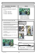
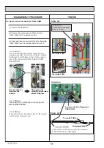
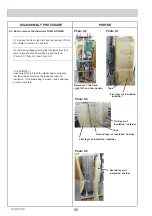
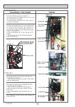
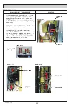
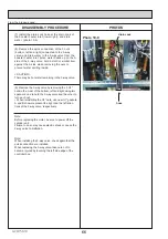
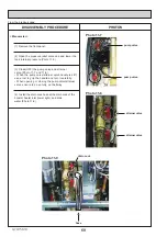
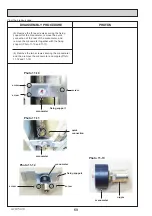
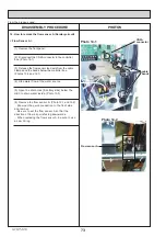
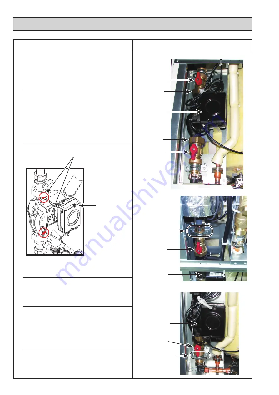
Photo 7-7
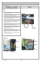
Photo 7-8
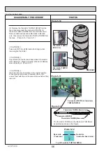
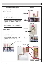
Figure 5
Photo 7-9
< Pump valve >
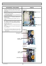
(8) Remove the pump valve stay by removing the 2
screws.(Photo 7-8 and 7-9)
・
Reuse the removed pump valve stay and the pump
valve stay fixing screws.
Note: Skip Steps (2) and (3) above when replacing the
pump valve only.
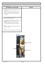
(9) Remove the pump valve by detaching the quick
connection.(Photo 7-8 and 7-9)
Take it off the pump valve on the water pump 1
earlier and slowly to drain water in pump 1 from the
drain valve.
:KHQUHLQVWDOOLQJWKHTXLFNFRQQHFWLRQXVHQHZ
O-ring.
From the previous page.
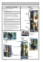
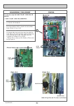
(7) Remove the water pump1 by removing the two G1
1/2” nuts using the two spanners: one to hold the G1
1/2” nut and the other to turn the other side of G1 1/2”
nut. Remove the water pump by sliding it horizontally.
(Photo 7-7 and Figure 5).
:KHQUHLQVWDOOLQJWKH*´QXWVXVHQHZ*´
gaskets.
6HWWKHZDWHUSXPSLQWKHZD\WKDWWKHVWDPSHG
flowarrow pointing up.
(6) Close (OFF) the pump valve (Photo 7-7)
:KHQWKHSXPSYDOYHKDQGOHLVVWLIIXVHDWRROWRJULS
the handle and turn it carefully.
:KHQRSHQLQJRUFORVLQJWKHSXPSYDOYHHQVXUHWR
GRVRIXOO\QRWKDOIZD\
pump valve
pump valve
pump valve
pump valve
pump valve stay
and 2 screws
pump valve stay
and 2 screws
Nut of the
pump valve
Nut of the
pump valve
water pump1
water pump1
When fixing water pump1
in place with the spanner,
use these flat sections.
water pump1
water pump1

