- 4 -
REPLACEMENT OF THE MAIN PCB ASSY
Outline
When replacing the MAIN PCB ASSY, transfer the factory
adjustment data from the old MAIN PCB ASSY to the new
MAIN PCB ASSY to write the DDC data into the new MAIN
PCB ASSY. There are three ways to transfer the data as
follows:
(1) Replace the EEPROM (U25).
(2) Follow “Electrical Adjustments” when the EEPROM on
the old MAIN PCB ASSY is defective.
(3) Read and transfer the data referring to “How to Read
and Transfer the Data” when you can’t replace the
EEPROM.
It is recommended to replace the EEPROM on which the data
are stored because it is the most quick and effective way.
Necessary tools
- Projector
- Personal computer (PC)
(Microsoft
®
WIndows
®
98/Me/XP installed)
- RS-232C cable
- Program folder “ChangePwbMAIN_XD430”
How to read and transfer the data
1. Preparation
1. Connect the projector of which MAIN PCB ASSY should
be replaced and the PC using the attached RS-232C
cable.
2. Connect the power cord to the projector. Make sure that
the POWER indicator illuminates red.
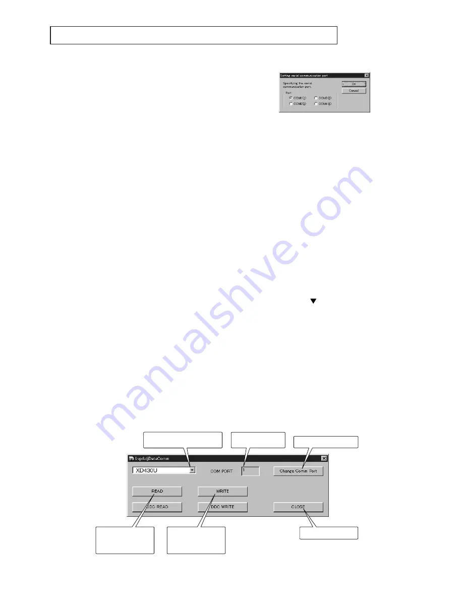
3. Start the PC and copy the “ChangePwbMAIN_XD430”
folder onto the desktop.
4. Double-click “LvpAdjDataComm_v4_1.exe” in the
“ChangePwbMAIN_XD430” folder to start the data
transfer program.
5. Click “ChangeCommPort” and select the port which is
connecting the personal computer and projector.
6. Select the model to use.
2. How to read the factory adjustment data
When clicking “READ”, the data are automatically read. If
the error message “No response from Projector” is
displayed, check the connection between the personal
computer and projector or check the setting of COM port.
When the data reading is completed successfully, “Correct”
is displayed. The adjustment data are saved as
“XD430_WriteData.txt” in the Setting folder.
3. How to replace the MAIN PCB ASSY
1. Disconnect the power cord and replace the MAIN PCB
ASSY.
2. Connect the power cord again after replacing the MAIN
PCB ASSY and make sure that there are no errors
indicated.
4. How to transfer the factory adjustment data
Click “WRITE” to write the data. When the data transfer is
completed successfully, “Correct” is displayed.
5. Operation check
1. Disconnect the power cord, and then reconnect it.
2. Press the “MENU,” “
,” and “ENTER” buttons at the
same time.
3. Check the projector’s operation. When the MAIN PCB
ASSY has been replaced successfully, the projector
operates correctly.
Writes the factory
adjustment data from
the PC to the PCB.
Exits the application.
Reads out the factory
adjustment data from
the PCB to the PC.
Selects the model.
Selects the COM port.
COM port No. being
connected.
Main dialog window
COM port switching dialog window


