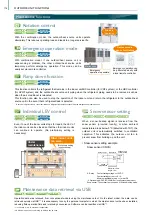
Demand control
Continuous heating operation
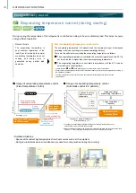
• System settings example
R2-Series
EP
R2-Series
P
WY-Series
WR2-Series
Y-Series
EP
Y-Series
P
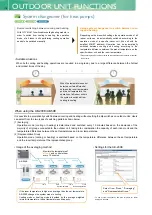
This function reduces the capacity of the outdoor/heat source unit by way of the external input to the outdoor unit.
The capacity of the outdoor unit can be reduced in steps, with patterns ranging from 2 to 12 control steps depending on
the system. The number of steps that can be set and the corresponding capacity are shown below.
• 2 steps (0-100%) • 4 steps (0-50-75-100%) • 8 steps (0-25-38-50-63-75-88-100%)
• 12 steps (0-17-25-34-42-50-59-67-75-84-92-100%)
Relay circuit BMS etc.
(local design)
External input adapter
PAC-SC36NA-E
CN3D
(Outdoor unit control board)
Units operate at the
preset capacity.
When power consumption is centrally-controlled within a building, the system can be forced to operate in the
capacity-save mode by receiving external signals.
Heating
operation
Heating
operation
Defrosting
operation
Heating
operation
Defrosting
operation
Heating
operation
Heating
operation
Defrosting
operation
Heating
operation
Defrosting
operation
Possible usage
Warm and
comfortable!
R2-Series
EP
R2-Series
P
Y-Series
EP
Y-Series
P
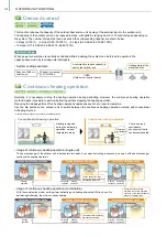
• Image of continuous heating operation (single unit)
A command to reduce capacity is
sent to the outdoor unit
The heat exchanger of the outdoor unit is divided into two parts. Even when defrosting is necessary, one part of the heat exchanger
continues the heating operation.
• Image of continuous heating operation (combination)
With the combination model, units perform defrosting and heating alternately. While one unit is
performing defrosting, the other continues heating.
Conventional heating operation
Continuous heating operation
Continuous heating operation
Conventional heating operation
Continuous heating operation
Continuous heating operation
During continuous heating
operation, the heating operation
continues, so the heating capacity
does not completely drop.
You can enjoy a
comfortable
environment that is
continuously heated.
Heating is stopped
during the defrosting
operation, so room
temperature drops.
Normally, it is necessary to stop the heating operation during defrosting. However, the continuous heating operation
method makes it possible to perform defrosting without stopping the heating operation.
Reducing the stoppage time of the heating operation suppresses any drop in room temperature.
Use the dip switch on the outdoor unit to switch between the continuous heating operation method and conventional
defrosting method.
* Heating capacity drops during continuous heating operation.
Conventional defrosting operation
Continuous heating operation
The two parts of the heat
exchanger perform defrosting
and heating alternately.
The units perform defrosting
and heating alternately.
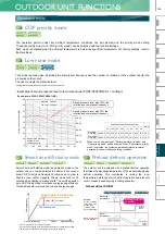
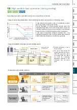
Operation at high outside temperatures
Selectable external static pressure of the outdoor unit
The static pressure specification for the outdoor unit can be selected (0, 30, 60, or 80 Pa).
This facilitates installation of the unit on each floor of a high-rise building or on balconies.
* The static pressure that can be set varies depending on the model.
* Noise level and power consumption vary depending on the static pressure setting.
* For details of the installation restrictions, refer to the DATABOOK.
PUHY-(E)P-Y(S)NW-A1
PURY-(E)P-Y(S)NW-A1
Conditions: Outdoor air temperature = 35°C (DB), Room temperature = 27°C (DB)
Built-up area with buildings and outdoor units
Installation on each floor of a high-rise building
Long exhaust hoods can be connected.
This facilitates installation of the unit on each
floor of a high-rise building or on balconies.
* PUHY-(E)P-Y(S)NW-A, PURY-(E)P-Y(S)NW-A
Maximum external static pressure
80 Pa
(local setting)
Example of flow analysis
R2-Series
EP
R2-Series
P
Y-Series
EP
Y-Series
P
R2-Series
EP
R2-Series
P
Y-Series
EP
Y-Series
P
* These images show the High efficiency R2 type.
• Models for use in outside temperatures of up to 52°C
If the passage of air is blocked in a built-up area, the
high temperature air discharged from the outdoor
units may linger around the units.
When the outdoor units are installed on the
balconies, the high temperature air discharged
from the units may be trapped in the balcony.
In built-up areas where the passage of air is blocked, the warm air that is discharged from the outdoor units
may cause high temperatures around the units. YNW has an expanded guaranteed operation range of up to 52°C
[125°F], so it can be used reliably even if the outdoor air temperature rises abnormally during the hot summer daytime.
VRF
Y-Series
VRF
Lineup
VRF
R2-Series
VRF
Zubadan
VRF
WY-Series
VRF
WR2-Series
VRF
S-Series
VRF
Indoor Units
Ventilation
Systems
Technologies and Functions
Remote Controller
Hot Water Solution
VRF
BC Controllers
VRF
S-Series
175
OUTDOOR UNIT FUNCTIONS
Содержание City Multi R2 Series
Страница 1: ...CM20AN E NZ VRF City Multi Product Catalogue ...
Страница 101: ...BC Controllers 101 ...
Страница 112: ...Indoor Units VRF 112 ...
Страница 114: ...Ceiling Cassette Type 4 Way Airflow Type 114 ...
Страница 122: ...Ceiling Cassette Type 2 Way Airflow Type 122 ...
Страница 128: ...Ceiling Concealed Type 128 ...
Страница 150: ...Wall Mounted Type 150 ...
Страница 154: ...Floor Standing Type 154 ...
Страница 181: ...Ventilation Systems 181 ...
Страница 190: ...Remote Controllers 190 ...
Страница 214: ...Hot Water Solution Air to Water Series 214 ...

