Heat Inter-Changer (HIC) circuit
A
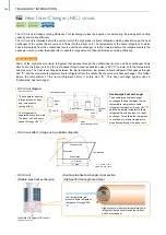
• HIC circuit diagram
• HIC circuit
(Double-pipe heat exchanger)
• HIC circuit effect: (Image using a Mollier diagram)
R2-Series
EP
R2-Series
P
WY-Series
WR2-Series
Y-Series
EP
Y-Series
P
Subcool
Condensation
Evaporation
Current
w/ HIC circuit
w/o HIC circuit
New
Expansion
Compression
Heat Inter-Changer (HIC) circuit
• Double-pipe heat exchanger cross section
(High-performance grooved pipe)
The HIC circuit increases cooling efficiency. This technology raises the degree of supercooling, increasing both cooling
capacity and cooling efficiency.
The HIC circuit is installed before the point at which the high pressure liquid refrigerant, which passes through the heat
exchanger of the outdoor/heat source unit, flows into the indoor unit. The temperature of the liquid refrigerant, to which
heat is discharged from the outdoor/heat source unit heat exchanger, is further lowered before the refrigerant enters the
expansion valve, to allow the evaporator to absorb a large amount of heat and increase cooling efficiency.
Cooling operation
Accumulator Compressor
Heat
Inter-Changer (HIC)
Outdoor
HEX
Indoor
HEX
LEV B
LEV A
A
Some of the high pressure liquid refrigerant that passes through the outdoor/heat source unit heat exchanger flows
directly into the indoor unit, and the rest passes through linear expansion valve (LEV) "C" to lower both the temperature
and pressure. The heat is exchanged between the low temperature, low pressure liquid refrigerant that passes through
LEV "C" and the moderate temperature liquid refrigerant from the outdoor/heat source unit heat exchanger. This further
lowers the temperature of the liquid refrigerant before it enters LEV "B." This heat exchange system uses a
"double-pipe" heat exchanger.
High pressure, moderate temperature liquid
refrigerant that passes through the outdoor
unit heat exchanger
The evaporator absorbs
a large amount of heat
and increases the
cooling effect.
The refrigerant is
separated; some flows into
the indoor unit, and some
passes through LEV "C."
HIC mechanism
Low temperature, low
pressure liquid refrigerant
that passes through LEV
"C"
LEV C
Double-pipe heat exchanger
The double-pipe heat exchanger
exchanges the heat between the low
temperature, low pressure liquid
refrigerant that passes through LEV "C"
and the moderate temperature liquid
refrigerant from the outdoor unit heat
exchanger. This allows the refrigerant
to cool down to a lower temperature
when flowing through the indoor unit.
*In case of Y-series
*In case of Y-series
The compressor is enclosed in a metal casing
to reduce noise.
In some models, a sound absorbing material is
applied to the metal casing to further reduce
noise.
The compressor is enclosed in a
metal casing to reduce noise.
Heated
compressor motor
Induction heating (IH) is used to heat the refrigerant that flows back into the compressor*. This method differs from the
conventional crankcase heater method (in which a belt heater is wrapped around the outside of the compressor) in that
heat is not applied from the outside; the refrigerant is heated from the inside, thus eliminating wasted heat.
* Normally, the compressor is heated while the outdoor unit is stopped to prevent liquid refrigerant from remaining in the compressor and to evaporate the liquid refrigerant in the
compressor.
*1. Power is supplied to the heater only with the 22HP and 24HP (P550 and P600) single modules
• Crankcase heater
power supply method
• IH power supply method
(without crankcase heater)
Crankcase heater
IH warmer
• During cooling, a serial flow path (flow through two of the heat exchangers split into
three, and then through the last heat exchanger) is used. With fewer paths, the
refrigerant flow rate is increased and the heat conductivity performance is improved.
In addition, the drop in heat exchanger capacity for per path prevents the refrigerant
stagnation and improves the condensing performance of the heat exchanger during
cooling.
• During heating, a parallel flow path (flow refrigerant simultaneously through all heat
exchangers split into three) is used. By flowing the refrigerant to all paths at the heat
exchanger inlets (by increasing the number of paths compared to cooling), pressure loss
in the heat exchanger is reduced, and the evaporator performance is improved.
* Increase in evaporator performance is compared to using the original number of cooling paths.
Comparison of EP300 (Y-Series)
SEER (cooling) with and without
variable path
(%)
110
70
80
90
100
60
50
40
30
20
10
0
without
Adaptive flow
control
with
Adaptive flow
control
SEER [-]
approx. 8% up
Adaptive flow control
Cooling
Heating
From
indoors
Compressor
To indoors
From
compressor
Switched
The refrigerant circuit flow adapts for both heating and cooling.
Adaptive flow control
Metal compressor enclosure
R2-Series
EP
R2-Series
P
Y-Series
EP
Y-Series
P
WY-Series
WR2-Series
*1
*1
R2-Series
EP
R2-Series
P
Y-Series
EP
Y-Series
P
(−18HP)
Y-Series
EP
164
TECHNOLOGY INTRODUCTION
Содержание City Multi R2 Series
Страница 1: ...CM20AN E NZ VRF City Multi Product Catalogue ...
Страница 101: ...BC Controllers 101 ...
Страница 112: ...Indoor Units VRF 112 ...
Страница 114: ...Ceiling Cassette Type 4 Way Airflow Type 114 ...
Страница 122: ...Ceiling Cassette Type 2 Way Airflow Type 122 ...
Страница 128: ...Ceiling Concealed Type 128 ...
Страница 150: ...Wall Mounted Type 150 ...
Страница 154: ...Floor Standing Type 154 ...
Страница 181: ...Ventilation Systems 181 ...
Страница 190: ...Remote Controllers 190 ...
Страница 214: ...Hot Water Solution Air to Water Series 214 ...


