[
IX
Troubleshooting ]
- 144 -
HWE15070
GB
Control Circuit
-6- Control Circuit
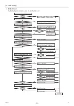
Troubleshooting transmission power circuit of outdoor unit
Check the voltage between No.1 and No.2 pins of the
CNS2 on the control board.
Check the wiring between the control board and power
supply board for the transmission line (CN102 and CNIT),
and check for proper connection of connectors.
Check the wiring between the control board and power
supply board for the transmission line (CN102 and CNIT),
and check for proper connection of connectors.
Is there a wiring
error or a connector
disconnection?
Check the voltage between No.5 and No.2 pins
of the CNIT on the control board.
Is the voltage
measurement between
4.5 and 5.2 VDC?
Is there a connector
disconnection?
Fix the connector disconnection.
Replace the M-NET board
Replace the control board.
Replace the M-NET board
Replace the M-NET board
Replace the noise filter.
Connect the noise filter CN4, and then turn the power on.
Replace the noise filter.
Replace the noise filter.
Check and fix any power supply wiring and main power
supply problems found.
Disconnect the noise filters CN4 and CN5, and then
replace F4, then turn the power on.
Fix the wiring and connector
disconnection.
Check for shorted transmission
line or power feed collision for
centralized control.
Replace the control board.
Check the voltage between No.1 and No.2 pins of the
CN102 on the power supply board for the transmission line.
Check the voltage between No.1 and No.3 pins of
the noise filter CN4.
Check the voltage between No.1 and No.3 pins of
the noise filter CN5.
Check the noise filter F4 fuse.
Check the voltages among TB22 and TB24 on the
noise filter.
Check the voltage between L2 and N at the power supply
terminal block TB1.
DC24 ~ 30V
DC24 ~ 30V
DC24 ~ 30V
DC279 ~ 374V
DC279 ~ 374V
F4 blown
F4 blown
F4 blown
AC198 ~ 264V
AC198 ~ 264V
DC24 ~ 30V
Turn on the
power again.
YES
YES
YES
YES
YES
YES
YES
YES
YES
YES
YES
YES
YES
YES
YES
NO
NO
NO
NO
NO
NO
NO
NO
NO
NO
NO
NO
NO
NO
NO
YES
NO
Check the voltage at the indoor/outdoor
transmission terminal block (TB3) of outdoor unit.
DC 24 ~ 30 V
DC 24 ~ 30 V
Check the voltage at TB3 after removing transmission line from TB3.
Check voltage of terminal block for centralized control (TB7).
Check voltage of TB7 by removing transmission line from TB7.
Check if the indoor/outdoor transmission line is not
short-circuited, and repair the problem.
Check whether the transmission line is disconnected,
check for contact failure, and repair the problem.
Replace the control board.
0000001906.book 144 ページ 2015年11月5日 木曜日 午前11時55分
Содержание CAHV-P500YB-HPB
Страница 1: ......
Страница 7: ...CONTENTS HWE15070 GB ...
Страница 9: ... 2 HWE15070 GB ...
Страница 19: ... 12 HWE15070 GB ...
Страница 37: ... 30 II Restrictions GB HWE15070 ...
Страница 39: ... 32 HWE15070 GB ...
Страница 48: ... 41 HWE15070 GB IV Remote Controller 1 Using the Remote Controller 43 2 Function Settings 48 ...
Страница 49: ... 42 HWE15070 GB ...
Страница 57: ... IV Remote Controller 50 HWE15070 GB ...
Страница 58: ... 51 HWE15070 GB V Electrical Wiring Diagram 1 Electrical Wiring Diagram 53 ...
Страница 59: ... 52 HWE15070 GB ...
Страница 65: ... 58 V Electrical Wiring Diagram GB HWE15070 ...
Страница 66: ... 59 HWE15070 GB VI Refrigerant Circuit 1 Refrigerant Circuit Diagram 61 2 Principal Parts and Functions 62 ...
Страница 67: ... 60 HWE15070 GB ...
Страница 71: ... VI Refrigerant Circuit 64 HWE15070 GB ...
Страница 73: ... 66 HWE15070 GB ...
Страница 111: ... 104 HWE15070 GB ...
Страница 117: ... VIII Test Run Mode 110 HWE15070 GB ...
Страница 119: ... 112 HWE15070 GB ...
Страница 163: ... IX Troubleshooting 156 HWE15070 GB ...
Страница 164: ... 157 HWE15070 GB X Attachments 1 R407C saturation temperature table 159 ...
Страница 165: ... 158 HWE15070 GB ...
Страница 167: ... X Attachments 160 HWE15070 GB ...
Страница 168: ......

