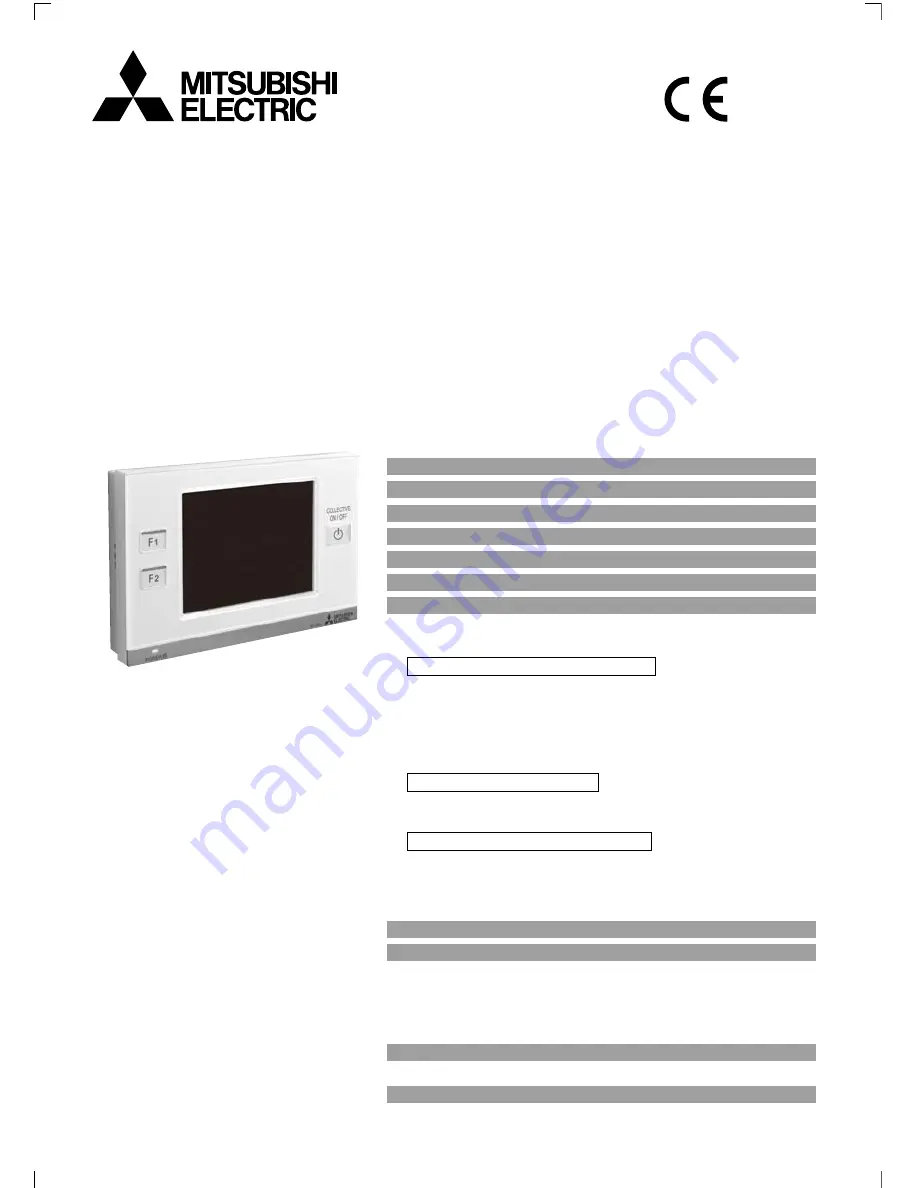
background image

Before using the controller, read this 

Instruction Book carefully to ensure 

proper operation.

Retain this Instruction Book for future 

reference.

Make sure that this manual as well as the 

Installation Manual are passed on to any 

future air condition system users.

To ensure safety and proper operation of 

the unit, the unit should only be installed 

by qualified personnel.

Air-conditioner Control System
ADVANCED TOUCH CONTROLLER

MODEL

AT-50A

INSTRUCTION BOOK

Safety Precautions .............................................................. 2

Function List ........................................................................ 4

Names and Functions of Controller Components................ 6

Screen Configuration [HOME screen]

 ................................. 8

Buttons [HOME screen]

 ..................................................... 10

Icon Displays [HOME screen]

............................................ 12

Basic Operations ............................................................... 16

Screen selection ......................................................................... 16

Group selection .......................................................................... 17

Operating the Air conditioning unit group ................................... 18

ON/OFF operation ........................................................................ 18

Mode ............................................................................................. 18

Temperature setting ...................................................................... 20

Interlocked ventilation units(LOSSNAY)/Fan speed/Air direction/Louver settings ....... 21

"Disable scheduled operation" button ........................................... 22

Operating the LOSSNAY group .................................................. 22

Mode ............................................................................................. 22

Fan speed setting ......................................................................... 22

Operating the General equipment group .................................... 22

ON/OFF operation ........................................................................ 22

Multiple group selection screen .................................................. 23

Disabling functions ..................................................................... 23

Menu Screen ..................................................................... 24

Usage - Main Menu Settings ............................................. 26

Operation Setting ....................................................................... 26

Restriction Settings .................................................................... 42

Control Panel .............................................................................. 50

System Management ................................................................. 57

Maintenance ...................................................................... 61

Touch Panel Cleaning screen ..................................................... 61

Troubleshooting ................................................................. 62

Содержание AT-50A

Страница 1: ...s 6 Screen Configuration HOME screen 8 Buttons HOME screen 10 Icon Displays HOME screen 12 Basic Operations 16 Screen selection 16 Group selection 17 Operating the Air conditioning unit group 18 ON OFF operation 18 Mode 18 Temperature setting 20 Interlocked ventilation units LOSSNAY Fan speed Air direction Louver settings 21 Disable scheduled operation button 22 Operating the LOSSNAY group 22 Mode...

Страница 2: ...ere is a risk of leaking flammable gas If flammable gas accumulates around the controller it may ignite and cause a fire or explosion Properly dispose of the packing materials Plastic bags pose suffocation hazard to children To reduce the risk of injury or electric shock before spraying a chemical around the controller stop the operation and cover the controller To reduce the risk of injury or ele...

Страница 3: ...units can be controlled from the AT 50A 1 Function Description Page Restriction Settings Lock Buttons Locks the following buttons Collective ON OFF F1 F2 and Main Menu Locks the following functions ON OFF Mode Set Temp Fan Speed and Schedule ON OFF 11 23 42 Set Temperature Range Limit Limits the available temperature range for the local remote controllers each group or all groups 44 Prohibit Remot...

Страница 4: ...ed from the Collective Operation panel 5 Power indicator The power indicator lights up when the power to AT 50A is turned on Unlit Power OFF Lit Power ON Touch panel Buttons 1 When the button is pressed while the operation is prohibited the LED will blink twice 2 Buttons 2 3 and 4 are available only on the HOME screen Names and Functions of Controller Components Product features 3 1 2 4 5 The AT 5...

Страница 5: ...s the GRID zoom out screen Displays the GRID zoom in screen Displays the LIST screen Displays the GROUP screen Displays the Main Menu screen GRID screen Zoom out screen To the GRID zoom in screen To the GRID zoom out screen Zoom in screen HOME screen To the GROUP screen To the GRID screen To the LIST screen To the GRID screen To the Main Menu screen To the HOME screen GROUP screen To the LIST scre...

Страница 6: ...gInterlocked ventilation LOSSNAY Air direction Fan speed Louver setting button Operation differs depending on the operation mode Operation mode 1 Turns ON OFF the units in the group whose Group icon is touched Operation mode 2 Switches the Group icon between Selected checked and Deselected unchecked Default Displays the check mark when Group icon is touched Operation mode 3 Directly moves to the G...

Страница 7: ...re registered to a group current indoor temperature on the main indoor unit is displayed Interlocked ventilation LOSSNAY Displays when there are ventilation units interlocked with the air conditioning indoor units in the group Icon color indicates the operation status Blue ON Black OFF General equipment icon Displays the General equipment type 3 LIST screen Display selection button Display selecti...

Страница 8: ...p communication error occurs Filter sign Displays when filter needs maintenance During scheduled operation Displays during scheduled operation When the Disable scheduled operation button is enabled Displays when the Disable scheduled operation button is enabled Room temperature Display ranges 8 39ºC 46 102ºF When the room temperature is beyond the range 8ºC 46ºF or 39ºC 102ºF will blink on the dis...

Страница 9: ...lt is set to the operation mode 2 Refer to P41 for changing the mode Operation mode 2 appears in the area marked 2 Allows the user to select groups to be operated Moves to the Group screen Touch the Group icon 1 to select the group to be operated Groups can be selected on the GRID or the LIST screens Touch the Group icon 1 to switch between displaying check marks selected and hiding check marks de...

Страница 10: ...indicator and the function name The indicators on the buttons show which functions are assigned to which buttons Indicator Function Collective Operation button Before using the Collective Operation buttons the groups to execute collective settings on must be selected and the parameters must be set from Main Menu Operation Setting Collective Operation Setting If appears on an icon of a given functi...

Страница 11: ...ir direction varies depending on the model D Louver useable only while the unit is in operation D does not appear when the model does not have this function After setting A through D touch the OK button A C B D Stop Low High Setting 1 Setting 2 Setting 3 Setting 4 Setting 5 Swing Auto Quiet Low Medium High Auto ON OFF Touch 4 to show the Interlocked ventilation units LOSSNAY Fan speed Air directio...

Страница 12: ...ot appear Fan speed setting Touch 3 to access the fan speeds in the order Low High The selected fan speed will appear in the area marked 4 2 1 3 4 Multiple group selection screen To operate the Air conditioning unit group Allows the user to collectively operate all groups that are selected on the GRID or LIST screen When selected groups include two or more unit types select the unit type to be ope...

Страница 13: ... are available P41 2 Restriction Settings 1 Lock Buttons Locks the buttons and the functions on the AT 50A P42 2 Set Temperature Range Limit Sets the temperature range for the local remote controllers P44 3 Prohibit Remote Controller Locks the buttons on the local remote controllers ON OFF Mode Set Temperature and Filter Reset buttons P46 4 Operation Mode Selection Limit Limits the operation mode ...

Страница 14: ...Use to assign unique operation patterns for specific dates up to seven days in advance including the current date Maximum 5 patterns The initial date time setting is 1 1 2011 12 00AM If the clock is set forward the operations that were scheduled to have taken place before the new time will be cancelled A Setting the date time and display format Date tab Time tab 4 5 Main Menu Operation Setting Tim...

Страница 15: ...as follows 1 Touch the Seasonal settings button on the Select Group and Days Date screen The Seasonal settings button appears only on the Weekly screen 2 Touch the button 1 and select the use or non use of Weekly2 Use Weekly2 Do not use Weekly2 3 Use the 2 buttons to select the use or non use of Weekly1 and the effective period for Weekly2 If Weekly2 is set to Do not use Weekly2 the effective peri...

Страница 16: ...n red and they will not be executed Touch the buttons to check the actions for each scheduled event Refer to P34 for icon definitions Operation pattern numbers Schedules events for the selected pattern 5 On the Edit Pattern screen touch an event number to edit its contents 1 The scheduled actions for each event will be displayed over two pages Use the scroll buttons to switch between the pages 2 O...

Страница 17: ... next to the button to activate the Copy Paste Delete and Insert buttons Copying pasting deleting and inserting settings 6 Set the time and the actions for the selected event number Usage Main Menu Settings Operation Setting cont d 1 Touch the item to be copied Items that can be copied include the weekly schedule for a group the pattern assigned to a specific day or the event that is scheduled to ...

Страница 18: ... button In this case the settings that were made on the Collective Operation Setback screen will override the settings made on the Setback Control screen and the scheduled operation will not run 1 Touch the C Setback Control button on the Time and Schedule screen 2 Read the pop up message and touch the OK button to confirm 1 6 4 5 7 When the temperature drops below the lower limit temperature heat...

Страница 19: ...ow that corresponds to the group whose schedules you want to check Touch the pattern number under a specific day to check the day s schedule that appears under the pattern numbers 4 Touch the buttons to check the actions for each scheduled event Touch the Close button to return to the previous screen 5 To change the schedule settings touch the Return button to return to the Time and Schedule scree...

Страница 20: ...s whose temperature setting is different from the one for the collective setting will appear underlined 4 Select the groups to include from the Group buttons labeled A By default all groups are selected 5 Touch the B Save button The minimum difference between the upper and lower limits is 4ºC 8ºF The temperature range that can be set depends on the connected units The groups that do not support th...

Страница 21: ...nd Filter Sign Reset settings from the local and other system controllers The settings that can be locked or unlocked depend on the type of group Indoor unit groups LOSSNAY groups 1 ON OFF 2 Mode 3 Set temperature 4 Filter Sign reset 1 Touch the 6 RC Prohibition button on the Collective Operation Setting screen 2 Read the pop up message and touch the OK button to confirm 3 Select the groups to inc...

Страница 22: ...be locked are the ones that appear on the HOME screen 4 On the HOME screen the icon will appear on the buttons that are locked Save button Saves the settings Category button Enable Disable Lock button Use these buttons to select the items to be locked when the operation lock button is enabled 1 2 3 To log in 1 Enter the login password from the 1 keyboard on the touch panel Touch 2 to delete a char...

Страница 23: ...2 3 Usage Main Menu Settings Restriction Settings cont d 5 Use the 4 buttons shown in the pop up window at right to set the range for each operation mode Cooling Heating and AUTO The temperature setting range and the operation mode that can be set depend on the indoor unit and remote controller models Operation from the local remote controllers that are connected to Mr SLIM cannot be prohibited fr...

Страница 24: ...ts four groups Group buttons Displays group numbers Touch the button for a specific group to edit its settings Edit button Edits the temperature range for the selected group Select All button Selects all groups 1 2 3 When appears on the Prohibit Remote Controller button this function will not be available 3 Click on the 2 Group button on the Prohibit Remote Controller screen to select the groups a...

Страница 25: ...ection to specific operation modes with this controller or the local remote controller for all groups can be limited For example the mode selection can be limited according to the season Cooling mode limit winter heating mode limit summer cooling heating mode limit between seasons 1 Touch the 4 Operation Mode Selection Limit button on the Restriction Settings screen 2 Touch the 1 button to set the...

Страница 26: ...y Format screen 1 3 to switch between ºC and ºF Main Menu Control Panel Display Format Display Format screen 1 3 1 2 3 4 1 2 3 4 5 6 7 Usage Main Menu Settings To show or hide the room temperature Touch the 3 Room Temperature button on the Display Format screen 1 3 to switch between Show and Hide To show or hide the Cooling Heating mode icon during Auto mode when the operation mode is enabled Touc...

Страница 27: ...the b Copy and c Paste buttons 4 Touch the 5 Save button 0 Group Name Setting screen a b c 5 Character input screen To enter a character string 1 Touch 1 or to select upper case alphabets lower case alphabets or numerical and other symbols 2 Enter characters from the 2 keyboard Scroll the screen up and down with the 3 buttons to see all characters To correct a character move the cursor over the ch...

Страница 28: ... or F2 so that the checkmark will appear as Check the check mark in the F1 column to assign a function to F1 and check the check mark in the F2 column to assign a function to F2 Touch the button again so that the button will appear as to cancel the selection 2 Touch the 3 Save button Main Menu Control Panel 3Adjusting the volume and brightness Main Menu Control Panel Volume Control To adjust the b...

Страница 29: ...ng the Error or Filter Sign 1 Touch the 1 Malfunction tab to check the number of errors the names of the group in which the errors occurred the addresses of the error source units and the error codes Main Menu System Management Status List To check the error 1 2 Touch the 1 Status List button on the System management screen To reset the error 1 Touch the 1 Malfunction tab 2 Touch the 2 All Reset b...

Страница 30: ...e Cooling or Heating mode all at once in the afternoon for example without the need to manually change the mode via each remote controller This function should not be used in conjunction with the System Changeover function on the outdoor unit or other system controllers When the System Changeover mode is set to Auto the operation mode is selected based on the demands of the majority of the group t...

Страница 31: ...tative Group will be displayed To designate a different group as the Representative Group select a new group on the screen that appears shown right when the 2 Representative Group button is pressed and then touch the OK button 3 Block No Displays the block number All units in each group are operated in the same operation mode The AT 50A automatically creates blocks based on the refrigerant pipe co...

Страница 32: ...lled by the AT 50A will stop The AT 50A controller low level system controllers or local remote controllers will not respond until the emergency stop signal input is removed When the emergency stop signal is removed the operation status before the signal was received will be restored Solution Solution Solution 1 Not for use with a generic DC power supply device Use the power supply unit for transm...

Страница 33: ...ct at hand is based on the following EU regulations Low Voltage Directive 2006 95 EC Electromagnetic Compatibility Directive 2004 108 EC HEAD OFFICE TOKYO BLDG 2 7 3 MARUNOUCHI CHIYODA KU TOKYO 100 8310 JAPAN Authorized representative in EU MITSUBISHI ELECTRIC EUROPE B V HARMAN HOUSE 1 GEORGE STREET UXBRIDGE MIDDLESEX UB8 1QQ U K ...

Отзывы: