Chapter 1
Chapter 2
Chapter 6
Contents
Chapter 3
Chapter 5
System Board
Chapter 3
LS PRO HARDWARE TECHNICAL REFERENCE 3/7
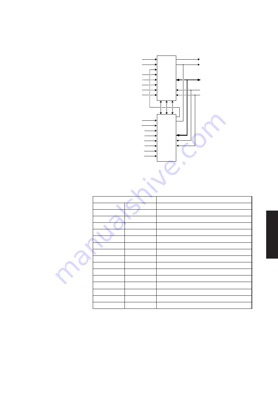
The following illustration shows the maskable interrupt structure.
IRQ0
IRQ1
IRQ3
IRQ4
IRQ5
IRQ6
IRQ7
IRQ8
IRQ9
IRQ10
IRQ11
IRQ12
IRQ13
IRQ14
IRQ15
INTR
INTA
8-BIT
DATA
BUS
ADDRESS
BUS
MASTER
CONTROLLER
SLAVE
CONTROLLER
SA0
IOR, IOW
XD0 to XD7
D0 to D7
0
1
2
3
4
5
6
7
0
1
2
3
4
5
6
7
A0
RD,WR
INT
INTA
INT
INTA
D0 to D7
RD,WR
A0
List of hardware
The interrupts are allocated to hardware functions in the priorities shown in the
interrupts
following table. IRQ0 is the highest priority.
Interrupt level
Function
IRQ0
Timer
IRQ1
Keyboard
IRQ2
Slave controller input
IRQ8
Real time clock
IRQ9
Token ring module
IRQ10
Ethernet port
IRQ11
Security
IRQ12
Mouse
IRQ13
Coprocessor exception
IRQ14
Hard disk controller
IRQ15
Digital audio
IRQ3
Reserved
IRQ4
Serial port
IRQ5
Reserved
IRQ6
Floppy disk controller
IRQ7
Parallel port
Note
IRQ0 and IRQ13 are both used inside the SCAMP chip. Neither emerges for use on the system
board.
Содержание Apricot LS Pro
Страница 1: ...apricot HARDWARE TECHNICAL REFERENCE MITSUBISHI ELECTRIC LS Pro ...
Страница 2: ...HARDWARE TECHNICAL REFERENCE ...
Страница 6: ...CONTENTS ...
Страница 9: ...Chapter 1 INTRODUCTION ...
Страница 14: ...Chapter 2 SYSTEM UNIT ...
Страница 37: ...Chapter 3 SYSTEM BOARD ...
Страница 60: ...Chapter 4 PERIPHERAL ITEMS ...
Страница 91: ...Chapter 5 MEMORY AND I O USAGE ...
Страница 118: ...Appendix A SPECIFICATIONS ...
Страница 125: ...Appendix B REVISION C SYSTEM BOARD ...
Страница 130: ...ERROR BEEP CODES Appendix C ...
Страница 134: ...INDEX ...


