1. Camera Installation
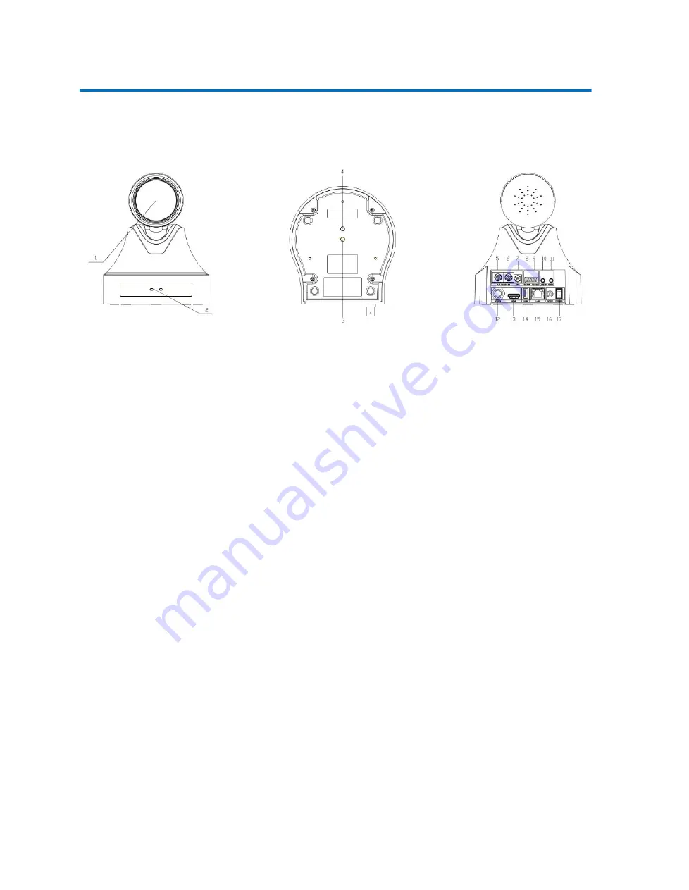
1.1 Camera Interfaces
Figure 1.1 Product Interfaces
1. Camera Lens
7. Rotary DIP Switch
13. HDMI Output Interface
2.
Remote Control Receiving
Indicator
8. RS485 Input (left +, right-)
14.USB2.0 Interface (U-disk memory)
3.
Tripod Screw Hole
9. RS422 Input
15. LAN Port
4.
Screw Hole for Tripod
10. Audio Input Interface (Line-in)
16. DC12V Input Power Supply
Socket
5. RS232 Control Interface
(
Input
)
11. CVBS Output Interface
17. Power Switch
6. RS232 Control Interface
(
Output
)
12. SDI Interface
1.2 Mounting Brackets
Notes:
Ceiling or wall mounting brackets can only be mounted on template and concrete wall.
For safety reason, plasterboard is not recommended.
1)
Wall Mounting
Содержание UV520-ST
Страница 1: ...FULL HD PTZ CAMERA User Manual V1 0 ...
Страница 6: ...2 Ceiling Mounting ...
Страница 7: ......


