5
MF01
–
005
–
010
–
R6
MP
–
A26
MODEL
OPTION PARTS
PORT SIZE
OUTPUT SPEC.
FLOW RATE
RANGE
R6
: ø6 mm, for flow rate range
005, 010, 050, 100, 500.
R8
: ø8 mm, for flow rate range
101, 201.
F1C
: Rc1/8", with internal threads,
for flow rate range
005, 010, 050, 100, 500
F4C
: Rc1/4", with internal threads,
for flow rate range 101, 201
010
: 2 NPN
Analog output 1 ~ 5 V
011
: 2 NPN
Analog output 4 ~ 20 mA
02
: 2 NPN RS485
030
: 2 PNP
Analog output 1 ~ 5 V
031
: 2 PNP
Analog output 4 ~ 20 mA
04
: 2 PNP RS485
005
: 500 (ml/min)
010
: 1000 (ml/min)
050
: 5 (l/min)
100
: 10 (l/min)
500
: 50 (l/min)
101
: 100 (l/min)
201
: 200 (l/min)
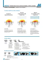
Thermal mass flwo sensor principles
Order example
Mounting accessories
Symmetric
temperature profile
(a) No flow
In the absence of flow, the heat
from the heater spreads evenly
left and right, so the temperature
distribution is like (a).
(b) Small flow
When flow begins, the inlet side
is cooled by the flow, the outlet
side is warmed by the heat of the
inlet side of the heater, and the
temperature distribution is like (b).
(c) Large flow
When the flow increases, it
becomes a distribution like (C).
Since the temperature distribution
before and after the heater is
proportional to the flow rate, the
flow rate can be determined from
the ratio.
Temperature
Sensor 1
Temperature
Sensor 1
Temperature
Sensor 1
Temperature
Sensor 2
Temperature
Sensor 2
Temperature
Sensor 2
Heating
Element
Heating
Element
Heating
Element
Skewed
temperature profile
Small Flow
Skewed
temperature profile
Large Flow
MODEL
DIGITAL FLOW SENSOR
( INSTRUCTION MANUAL )
MF01
Thermal mass flow sensor principles / Order example
A26
: Mounting bracket (BT-26)
B4
: Panel adapter (PA-G)
C4
: Panel a Front protective lid (PA-H)
A26
B4
C4

