Miltenyi Biotec UltraMicroscope II Скачать руководство пользователя страница 1

UltraMicroscope II Imaging System

User manual

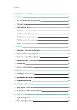
Содержание UltraMicroscope II

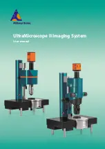
Страница 1: ...UltraMicroscope II Imaging System User manual...

Страница 2: ...ess or organization Maximal care has been taken by Miltenyi Biotec in the preparation of this user manual However Miltenyi Biotec shall not be liable for any technical or editorial errors or omissions...

Страница 3: ...by Miltenyi Biotec B V Co KG Friedrich Ebert Stra e 68 51429 Bergisch Gladbach Germany Phone 49 2204 8306 0 Fax 49 2204 85197 macsde miltenyi com www miltenyibiotec com LaVision BioTec GmbH a Miltenyi...

Страница 4: ...could lead to improper or incorrect usage and result in damage to the instrument Improper usage could also cause severe personal injury death unpredictable results instrument malfunction and prematur...

Страница 5: ...rface 17 3 Installation 19 3 1 Components Zoom Body configuration 19 3 2 Accessories Zoom Body configuration 20 3 3 Components Super Plan configuration 20 3 4 Accessories Super Plan configuration 21 3...

Страница 6: ...e color z stack 37 7 2 1 Aligning the sample 37 7 2 2 Optimizing the measurement settings 39 7 2 3 Capturing an image 40 7 3 Capturing a multi color z stack 41 7 4 Capturing a mosaic image 42 8 Mainte...

Страница 7: ...ety and prevention of accidents Ensure safe working conditions and provide for sufficient light Safe working is only possible if solely trained personnel uses the instrument The training is a permanen...

Страница 8: ...fe practices or NOTICE indicates information considered important but not hazard related e g messages relating to property damage Symbols SAFETY WARNING THE DOCUMENTATION MUST BE CONSULTED IN ALL CASE...

Страница 9: ...e not legible or identifiable from a safe viewing distance Contact Miltenyi Biotec for replacement labels Figure 1 1 Hazard areas and safety symbols on the top side of the UltraMicroscope II Imaging S...

Страница 10: ...se the instrument if liquids have entered the inside of the instrument Protect the instrument against spilled liquids Do not allow liquids to enter the inside of the instrument Clean up spilled liquid...

Страница 11: ...azardous Follow local regulations regarding waste disposal Equipment damage Defective or inadequate equipment can cause a biological hazard Some decontamination methods may damage the instrument If pa...

Страница 12: ...at support a weight of 250 kg Do not install the instrument yourself Only trained Miltenyi Biotec personnel or personnel authorized by Miltenyi Biotec is allowed to install the instrument ERGONOMIC HA...

Страница 13: ...ltenyi Biotec products in accordance with the applicable WEEE and hazardous waste disposal legislation which may differ by country or region Electrical equipment may contain hazardous substances that...

Страница 14: ...1 IMPORTANT SAFETY INFORMATION 12...

Страница 15: ...with one of the following modules l the Zoom Body Module for easy handling in a multi user environment l the Super Plan Module that can deliver unprecedented image resolution and image quality and an...

Страница 16: ...ap available For the Super Plan configuration there are two laser configurations and two camera configurations available There are three different objectives and four dipping caps available This guara...

Страница 17: ...y configuration 1 Cable duct 3 Type label 2 Cable duct 4 Electronic interface 2 3 3 Front view Super Plan configuration Figure 2 3 Front view of the UltraMicroscope II Imaging System Super Plan config...

Страница 18: ...view Super Plan configuration Figure 2 4 Rear view of the UltraMicroscope II Imaging System Super Plan configuration 1 Cable duct 4 Type label 2 Controller connection 5 I O ports 3 Cable duct 2 INTRO...

Страница 19: ...nic interface Figure 2 5 Detail view of the I O ports and power switch 1 Power supply 4 Camera trigger 2 Jog wheel 5 PC connection 3 Detection unit 6 Power switch Figure 2 6 Detail view of the couplin...

Страница 20: ...2 INTRODUCTION 18...

Страница 21: ...sales representative Components included in the delivery Beam Combiner 150 000 484 White Light Laser 150 001 844 Light source up to 5 lasers of choice white light laser Objective lens 2x 2x Emission...

Страница 22: ...ument Additional accessories and consumables developed specifically for the system are available separately Refer to Table 3 4 and Table 3 5 For details visit www miltenyibiotec com or contact your lo...

Страница 23: ...g cap water for objective lens 4 MI PLAN 150 001 660 Dipping cap aqueous buffers for objective lens 4 MI PLAN 150 001 658 Dipping cap organic solvents for objective lens 4x MI PLAN 150 001 657 Dipping...

Страница 24: ...information Before installation ensure that your site is properly prepared The instrument should be installed on an optical table with vibration isolation that can carry a weight of at least 250 kg A...

Страница 25: ...The switched on devices are registered and checked 4 2 Switching off the instrument 1 Close the ImSpector software 2 Shut down the Windows system 3 Switch off the camera 4 Switch off the instrument 5...

Страница 26: ...ive window Live window Select left light sheet Activates the light sheet on the left hand side Settings 1 window Select both light sheets Activates the light sheets on both sides Settings 1 window Sel...

Страница 27: ...agents Immediately replace the waste bottle after unmounting and fasten the bottle closure to the new bottle Wear personal protective equipment such as gloves safety glasses etc as indicated in the sa...

Страница 28: ...2 Setting the parameters for the alignment 1 Start the ImSpector software 2 Select the appropriate Instrument Mode in the Measurement Wizard window for the ordered configuration such as Zoom Body 3 Se...

Страница 29: ...lect the Measurement tab and select the imaging solution used in the cuvette under Liquid 8 Set the exposure time to a value between 100 and 200 ms in the Camera view 9 Select the objective lens such...

Страница 30: ...5 PREPARING THE INSTRUMENT 28...

Страница 31: ...ning the central light sheet on the left hand side in the z plane Later the screw can be used for the fine adjustment of the z shift between the left and right The screws Z2 and Z4 are used for aligni...

Страница 32: ...aser beam Do not insert reflective objects into the cuvette Do not manipulate the alignment tool during alignment Before setting the light sheet path ensure that not any bubbles are present to the sid...

Страница 33: ...arper the lines the better is the z position 5 Decrease the sheet width to the standard refer to Setting the parameters for the alignment on page 26 6 Lower the objective lens and focus on the light s...

Страница 34: ...ofile 12 Right click on the dark gray part of the y axis and activate Grow This setting makes it easier to visualize the intensity of the light sheet 13 Use the knobs of the focusing unit l outer knob...

Страница 35: ...ne passes the pinhole Ensure that the light sheet focus is always in the center and the Optics sheet NA is at the maximum If necessary readjust the z direction 3 If only one line passes the pinhole in...

Страница 36: ...f interest over the light sheets passing the pinhole in the live window and activate the intensity profile 5 Check the adjustment by clicking the Brain button under Scan Range in the Settings 2 window...

Страница 37: ...e center of the mask of the alignment tool 2 Adjust the height of the lateral light sheets Start with the rear light sheet using the adjustment screw Z2 Refer to Figure 6 1 Use an Allen key to align t...

Страница 38: ...6 LASER ALIGNMENT 36...

Страница 39: ...holder to the sample holder frame 3 Place the sample holder frame into the cuvette NOTICE Ensure not to drop any medium into the microscope chamber 7 2 Capturing a single color z stack 7 2 1 Aligning...

Страница 40: ...the Settings 1 window and select the imaging solution used in the cuvette 8 Select the excitation and emission wavelengths for your sample under Filter for Measurement Channel Setup in software versi...

Страница 41: ...ement settings 1 Draw a rectangle over an illuminated and or a dark region If drawing is not possible click the ROI for active profile button on the right side of the live window twice 2 Click the Adj...

Страница 42: ...anged 7 2 3 Capturing an image 1 Move in the z direction to the starting position 2 Click Current Position Set as Zero in the Settings 2 window 3 Click the Take button under Scan Range Start 4 Move in...

Страница 43: ...The selected checkboxes are used 5 Move the slider under Laser Transmission Control while the filter is highlighted to set the laser power for each individual filter NOTICE Higher laser power will ble...

Страница 44: ...ion in the Measurement Wizard 2 Click the Mosaic tab in the xyz Table Visual XY window 3 Double click the green square representing the field of view The square will turn gray 4 Click and drag the bla...

Страница 45: ...7 SETTING UP AN EXPERIMENT 43 5 Enter a percentage value to set an Overlap 6 To start the measurement proceed as described under Capturing an image on page 40...

Страница 46: ...7 SETTING UP AN EXPERIMENT 44...

Страница 47: ...table cleaning agents on a soft cloth to wipe the instrument 1 Unplug the instrument 2 To disinfect wipe accessible surfaces with 70 ethanol or isopropanol 3 If necessary wipe the instrument with a da...

Страница 48: ...8 MAINTENANCE 46...

Страница 49: ...m Weight 47 kg w o laser source Nominal input voltage 12 V DC provided by external power supply Working conditions Temperature 15 27 C Humidity max 70 relative humidity noncondensing Storage condition...

Страница 50: ...43 mm Chromatic correction Dynamic 400 850 nm Sheet optics Illumination Uni and bidirectional Number of light sheets 1 6 Thickness 4 24 m Width 1 20 mm Numerical aperture 0 0135 0 135 Focus positionin...

Страница 51: ...duct conforms to the requirements of the following directives 2006 42 EC Machinery 2014 30 EU Electromagnetic compatibility 2014 35 EU Low voltage In case of any change to the product not executed or...

Страница 52: ...Supply of machinery Safety regulations 2008 Electromagnetic Compatibility Regulations 2016 Electrical Equipment Safety Regulations 2016 In case of any change to the product not executed or authorized...

Страница 53: ...entative or Miltenyi Biotec Technical Support at Miltenyi Biotec headquarters Miltenyi Biotec B V Co KG Friedrich Ebert Stra e 68 51429 Bergisch Gladbach Germany Phone 49 2204 8306 3803 technicalsuppo...

Страница 54: ...10 TECHNICAL SUPPORT 52...

Страница 55: ...notice shall include the product model and serial number if applicable and details of the warranty claim and b return the nonconforming or defective product to Miltenyi Biotec freight prepaid only aft...

Страница 56: ...T EXCEPT AS EXPRESSLY PROVIDED IN THIS WARRANTY STATEMENT MILTENYI BIOTEC HEREBY DISCLAIMS ALL OTHER WARRANTIES WHETHER EXPRESS OR IMPLIED ORAL OR WRITTEN WITH RESPECT TO THE PRODUCT INCLUDING WITHOUT...

Страница 57: ......

Страница 58: ...ris France Phone 33 1 56 98 16 16 macsfr miltenyi com Hong Kong Miltenyi Biotec Hong Kong Ltd Unit 301 Lakeside 1 No 8 Science Park West Avenue Hong Kong Science Park Pak Shek Kok New Territories Hong...

Отзывы: