
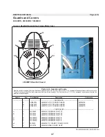


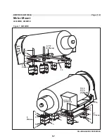


Service Connections
PELLERIN MILNOR CORPORATION
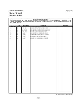
Table 2: Table of Piped Inlets
Description of
Connections
Source Requirements
Piping Specifications,
Comments
Compressed
air--hydraulic tilting
and non-tilt models
1/4" NPT, 85 - 110 PSI (5.97 -
7.73 kg.sq. cm.)
Cold water inlet
Hot water inlet
2" NPT 10 - 75 PSI (0.7 -5.27
kgs.sq. cm.)
Steam inlet
1 - 1/4" NPT 30 - 115 PSI (2.10 -
8.08 kgs. sq. cm.)
Compressed air--air
tilting models
3/4" NPT 85 - 110 PSI (5.97 - 7.73
kg.sq. cm.)
Compressed
air--hydraulic tilting
and non-tilting models
1/4" NPT 85 - 110 PSI (5.97 - 7.73
kg.sq. cm.)
Pipe material per plumbing code
2.1.
Piped Outlet Specification
—Piped outlet requirements are as follows (see dimensional
drawings for sizes and locations of connection points):
Table 3: Table of Piped Outlets
Description of
Connections
Destination Requirements or
Description
Piping Specifications
Drain
8" OD (not tilted)
Vent
4" Diameter
Rubber hose, PVC, or other
approved material per plumbing
code
2.2.
Precautions for Electrical Connections
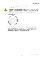
WARNING 3 : Electrocution Hazard
—Contact with high voltage can kill or seriously
injure you.
• All electrical connections must be made by a competent electrician.
1. Connections must be made by a competent electrician.
2. See the fuse and wire sizing information in the schematic manual and on the machine
nameplate.
3. “Stinger leg” if any, must be connected to terminal L3, never to terminals L1 or L2.
4. Only use BUSSMAN FUSETRON FRN (up to 250V), FRS (up to 600V), or similar lag fuses.
The nameplate fuse sizes must not be applied to standard fuses.
5. See nameplate for fuse and wire size. For wire runs more than 50 feet (15.24 meters),
increase by one wire size per each additional 50 feet.
6. Make the power and liquid supply electrical connections within junction box on the rear of
the machine.
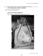
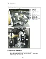
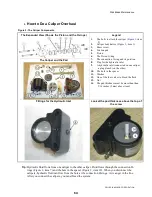
7. Verify all motor rotation as shown in FIGURE 1 (See the operating and troubleshooting
manual for more information). If the cylinder turns in the wrong direction, see note below.
Note 1:
Before shipping, all motors are properly phased for correct rotation. It is possible to reverse
the direction of rotation in a three-phase machine by interchanging the incoming power leads.
Therefore, the rotation of a three-phase machine must be observed and corrected when the machine is
first installed. If it is necessary to reverse the rotation, simply swap the incoming power lines to the
50
Содержание 48040M7K
Страница 2: ......
Страница 8: ......
Страница 9: ...Safety 1 5 ...
Страница 43: ...Installation 2 39 ...
Страница 56: ......
Страница 57: ...Drive 3 53 ...
Страница 59: ...Drive Components and Belt Installation PELLERIN MILNOR CORPORATION Figure 2 Detailed views 55 ...
Страница 93: ...Frame and Tilt 4 89 ...
Страница 101: ...Hydraulic Assemblies 5 97 ...
Страница 110: ......
Страница 111: ...Door Assemblies 6 107 ...
Страница 125: ...Water and Steam 7 121 ...
Страница 137: ...Chemical 8 133 ...
Страница 142: ......
Страница 143: ...Control and Sensing Assemblies 9 139 ...
Страница 149: ...Dimensional 10 145 ...
Страница 150: ......
Страница 151: ...147 ...