


PELLERIN MILNOR CORPORATION
4.
Setting Procedures
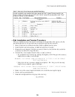
To protect against lateral creeping of the machine during operation (due to vibration),
roughen the area of the floor where the grout will be applied. Anchor bolts are required.
1. With the machine near the final location, unbolt the shipping skids. Observing all
precautions, lift the machine off its skids and lower the machine onto blocking. Shim the
blocking until the machine is level and approximately l" (25) clearance exists under each base
pad. Install anchor bolts as shown on the dimensional drawing, but do not tighten bolts until
grout is completely dry.
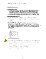
2. Apply grout between the existing foundation floor and the base pads, observing the following
considerations:
• Use only industrial strength non-shrinking grout. Pack or trowel by hand.
• If the grout after mixing is too thin (causing it to flow from under the base pads) install
temporary cardboard framing around pads to retain the grout until it cures.
CAUTION 3 : Vibration and Malfunction Hazard
—Voids under the base pads can
magnify vibration and cause unsatisfactory operation.
• Grout must displace total clearance between base pads and existing foundation
floor.
• Voids must not exist.
3. Tighten anchor bolts evenly using only one-quarter turn on each bolt before moving to the
next one. While tightening, frequently skip from front to back and right to left to insure
uniform tension. After tightening all bolts, check each bolt at least twice during the first week
of operation.
5.
Before Running Machine
CAUTION 4 : Machine Damage Hazard
—Machine can be damaged if shipping restraints
are improperly utilized. These include various bolts, brackets, weldments and safety stands
(painted red), and the vibration safety switch (tie wrapped).
• DO NOT remove shipping restraints until installation is complete.
• DO remove all shipping restraints before operating machine.
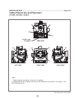
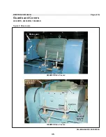
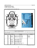
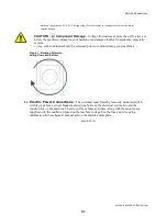
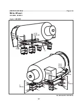
All machines are shipped with the shell locked to the mid frame by four hold down ring
weldments (two per side). Each weldment consists of a cone and cup arrangement. When
shipped, the shell mounted cone and the mid-frame mounted cup are locked together using a
center bolt and shims inserted under the weldment cup (
). Remove the center bolt and
shims before placing machine in service. Re-install the weldment as shown in
and store
the shims underneath the mid frame as shown in
. Retain center bolts in the event that the
machine is moved.
42
Содержание 48040M7K
Страница 2: ......
Страница 8: ......
Страница 9: ...Safety 1 5 ...
Страница 43: ...Installation 2 39 ...
Страница 56: ......
Страница 57: ...Drive 3 53 ...
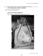
Страница 59: ...Drive Components and Belt Installation PELLERIN MILNOR CORPORATION Figure 2 Detailed views 55 ...
Страница 93: ...Frame and Tilt 4 89 ...
Страница 101: ...Hydraulic Assemblies 5 97 ...
Страница 110: ......
Страница 111: ...Door Assemblies 6 107 ...
Страница 125: ...Water and Steam 7 121 ...
Страница 137: ...Chemical 8 133 ...
Страница 142: ......
Страница 143: ...Control and Sensing Assemblies 9 139 ...
Страница 149: ...Dimensional 10 145 ...
Страница 150: ......
Страница 151: ...147 ...