
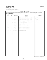


Fastener Torque Requirements
PELLERIN MILNOR CORPORATION
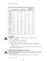
Table 4: Torque Values for Plated Fasteners Larger Than 5/16-inch
Bolt Grade
Grade 2
Grade 5
Grade 8
Grade BC
Bolt Size
Pound-feet
N-m
Pound-feet
N-m
Pound-feet
N-m
Pound-feet
N-m
3/8 x 16
15
20
23
31
33
44
29
38
3/8 x 24
17
23
26
35
37
49
--
--
7/16 x 14
24
32
37
50
52
71
46
61
7/16 x 20
27
36
41
55
58
78
--
--
1/2 x 13
37
49
56
76
80
106
70
93
1/2 x 20
41
55
64
85
90
120
--
--
9/16 x 12
53
70
81
110
115
153
101
134
9/16 x 18
59
79
91
122
128
174
--
--
5/8 x 11
73
97
113
150
159
212
139
186
5/8 x 18
83
110
127
172
180
240
--
--
3/4 x 10
129
173
200
266
282
376
246
329
3/14 x 16
144
192
223
297
315
420
--
--
7/8 x 9
125
166
322
430
455
606
398
531
7/8 x 14
138
184
355
474
501
668
--
--
1 x 8
188
250
483
644
682
909
597
796
1 x 12
205
274
528
716
746
995
--
--
1 x 14
210
280
542
735
765
1037
--
--
1 1/8 x 7
266
354
595
807
966
1288
845
1126
1 1/8 x 12
298
404
668
890
1083
1444
--
--
1 1/4 x 7
375
500
840
1120
1363
1817
1192
1590
1 1/4 x 12
415
553
930
1261
1509
2013
--
--
1 3/8 x 6
491
655
1102
1470
1787
2382
1564
2085
1 3/8 x 12
559
758
1254
1672
2034
2712
--
--
1 1/2 x 6
652
870
1462
1982
2371
3161
2075
2767
1 1/2 x 12
733
994
1645
2194
2668
3557
--
--
1.1.2.
With Threadlocking Compound
Table 5: Threadlocking Compound Selection by Bolt Size
Bolt Size
LocTite Product
1/4"
1/4" – 5/8"
5/8" – 7/8"
1" +
LocTite 222
OK
LocTite 242
OK
LocTite 262
OK
LocTite 272
High temperature
LocTite 277
OK
24
Содержание 48040M7K
Страница 2: ......
Страница 8: ......
Страница 9: ...Safety 1 5 ...
Страница 43: ...Installation 2 39 ...
Страница 56: ......
Страница 57: ...Drive 3 53 ...
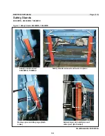
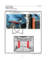
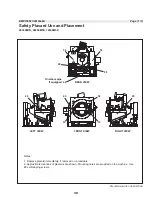
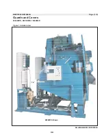
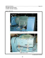
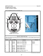
Страница 59: ...Drive Components and Belt Installation PELLERIN MILNOR CORPORATION Figure 2 Detailed views 55 ...
Страница 93: ...Frame and Tilt 4 89 ...
Страница 101: ...Hydraulic Assemblies 5 97 ...
Страница 110: ......
Страница 111: ...Door Assemblies 6 107 ...
Страница 125: ...Water and Steam 7 121 ...
Страница 137: ...Chemical 8 133 ...
Страница 142: ......
Страница 143: ...Control and Sensing Assemblies 9 139 ...
Страница 149: ...Dimensional 10 145 ...
Страница 150: ......
Страница 151: ...147 ...