background image

TM-4414 Page 3

Belt/Hydraulic Drive Generator

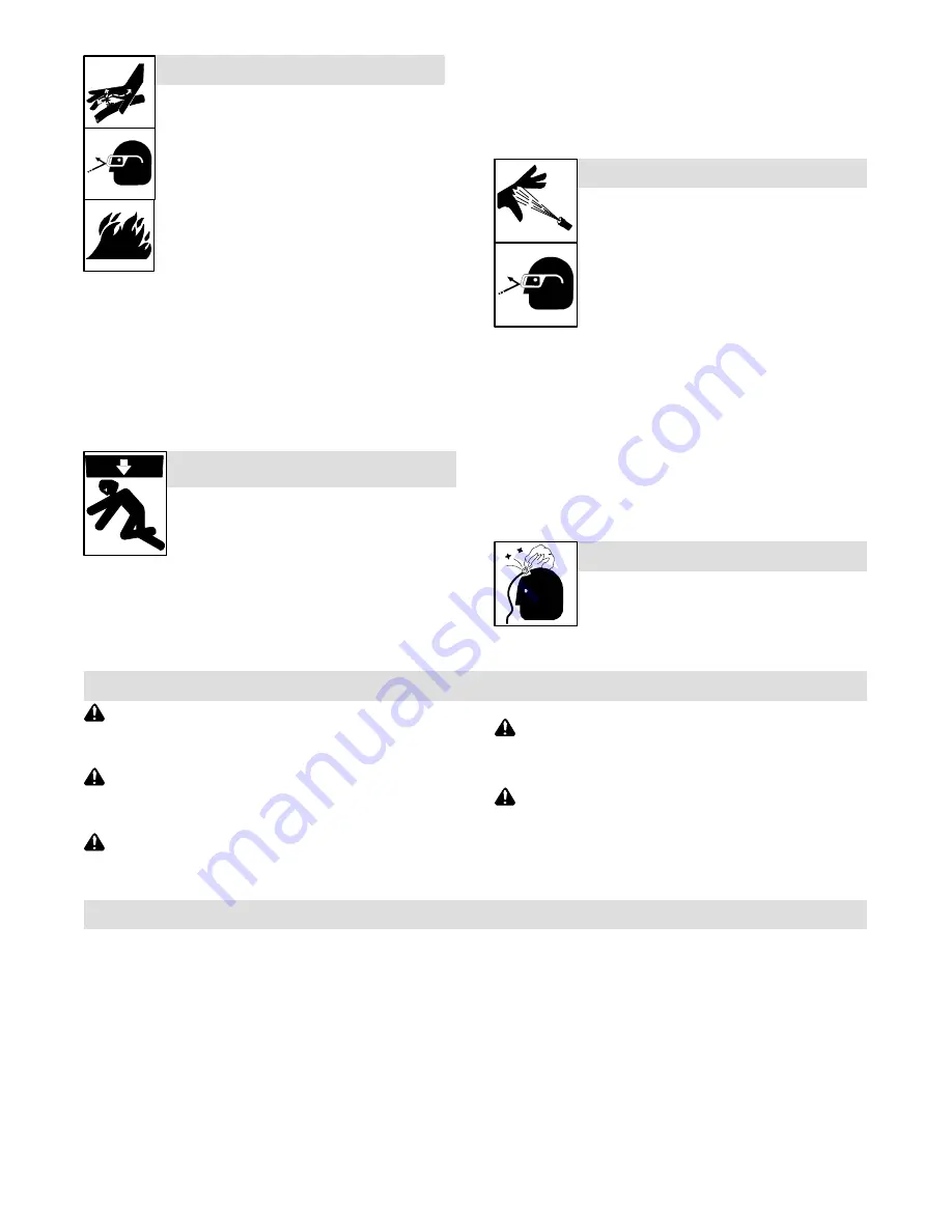
HYDRAULIC FLUID can injure or kill.

D

Before working on hydraulic system, turn off and

lockout/tagout unit, release pressure, and be sure

hydraulic pressure cannot be accidentally applied.

D

Relieve pressure before disconnecting or con-

necting hydraulic lines.

D

Check hydraulic system components and all con-

nections and hoses for damage, leaks, and wear

before operating unit.

D

Wear protective equipment such as safety

glasses, leather gloves, heavy shirt and trousers,

high shoes, and a cap when working on hydraulic

system.

D

Use a piece of paper or cardboard to search for leaks

−−

never use

bare hands.  Do not use equipment if leaks are found.

D

HYDRAULIC FLUID is FLAMMABLE

−−

do not  work on hydraulics

near sparks or flames; do not smoke near hydraulic fluid.

D

Reinstall doors, panels, covers, or guards when servicing is

finished and before starting unit.

D

If ANY fluid is injected into the skin, it must be surgically removed

within a few hours by a doctor familiar with this type of injury or gan-

grene may result.

COMPRESSED AIR EQUIPMENT can

injure or kill.

D

Before working on compressed air system, turn

off and lockout/tagout unit, release pressure,

and be sure air pressure cannot be accidentally

applied.

D

Do not work on compressed air system with unit running unless

you are a qualified person and following the manufacturer’s in-

structions.

D

Do not modify or alter compressor or manufacturer-supplied

equipment. Do not disconnect, disable, or override any safety

equipment in the compressed air system.

D

Keep away from potential pinch points or crush points created by

equipment connected to the compressed air system.

D

Do not work under or around any equipment that is supported only

by air pressure. Properly support equipment by mechanical

means.

COMPRESSED AIR  can injure or kill.

D

Before working on compressed air system,

turn off and lockout/tagout unit, release pres-

sure, and be sure air pressure cannot be acci-

dentally applied.

D

Relieve pressure before disconnecting or con-

necting air lines.

D

Check compressed air system components

and all connections and hoses for damage,

leaks, and wear before operating unit.

D

Do not direct air stream toward self or others.

D

Wear protective equipment such as safety glasses, hearing pro-

tection, leather gloves, heavy shirt and trousers, high shoes, and

a cap when working on compressed air system.

D

Use soapy water or an ultrasonic detector to search for

leaks

−−

never use bare hands.  Do not use equipment if leaks are

found.

D

Reinstall doors, panels, covers, or guards when servicing is

finished and before starting unit.

D

If ANY air is injected into the skin or body seek medical help im-

mediately.

TRAPPED AIR PRESSURE AND WHIPPING

HOSES can injure.

D

Release air pressure from tools and system be-

fore servicing, adding or changing attach-

ments, or opening compressor oil drain or oil fill

cap.

1-3. California Proposition 65 Warnings

Welding or cutting equipment produces fumes or gases

which contain chemicals known to the State of California to

cause birth defects and, in some cases, cancer. (California

Health & Safety Code Section 25249.5 et seq.)

Battery posts, terminals and related accessories contain lead

and lead compounds, chemicals known to the State of

California to cause cancer and birth defects or other

reproductive harm. Wash hands after handling.

This product contains chemicals, including lead, known to

the state of California to cause cancer, birth defects, or other

reproductive harm. 

Wash hands after use.

For Gasoline Engines:

Engine exhaust contains chemicals known to the State of

California to cause cancer, birth defects, or other reproduc-

tive harm.

For Diesel Engines:

Diesel engine exhaust and some of its constituents are

known to the State of California to cause cancer, birth

defects, and other reproductive harm.

1-4. EMF Information

Electric current flowing through any conductor causes localized electric

and magnetic fields (EMF). Welding current creates an EMF field

around the welding circuit and welding equipment. EMF fields may inter-

fere with some medical implants, e.g. pacemakers. Protective

measures for persons wearing medical implants have to be taken. For

example, restrict access for passers

by or conduct individual risk as-

sessment for welders. All welders should use the following procedures

in order to minimize exposure to EMF fields from the welding circuit:

1. Keep cables close together by twisting or taping them, or using a

cable cover.

2. Do not place your body between welding cables. Arrange cables

to one side and away from the operator.

3. Do not coil or drape cables around your body.

4. Keep head and trunk as far away from the equipment in the

welding circuit as possible.

5. Connect work clamp to workpiece as close to the weld as

possible.

6. Do not work next to, sit or lean on the welding power source.

7. Do not weld whilst carrying the welding power source or wire

feeder.

About Implanted Medical Devices:

Implanted Medical Device wearers should consult their doctor and the

device manufacturer before performing or going near arc welding,  spot

welding, gouging, plasma arc cutting, or induction heating operations.

If cleared by your doctor, then following the above procedures is recom-

mended.

Содержание TM-4414K

Страница 1: ...Visit our website at www MillerWelds com Description Belt Hydraulic Driven Generator For Welding Power Sources TM 4414K 2013 01 Belt Drive Generator Hydraulic Drive Generator Eff w LC199488...

Страница 2: ...INFORMATION ON OLDER UNITS This manual includes operating information for current units To obtain specific operating information for older models contact JLG Service at 1 877 554 5438...

Страница 3: ...RY OF OPERATION 8 SECTION 6 TROUBLESHOOTING 9 6 1 Troubleshooting Table 9 6 2 Troubleshooting Circuit Diagram For Welding Generator 12 6 3 Waveforms For Section 6 2 14 6 4 Power Board PC1 Testing Info...

Страница 4: ......

Страница 5: ...according to instructions in Troubleshooting Section before touching any parts MOVING PARTS can injure D Keep away from moving parts such as fans belts and rotors D Keep away from pinch points such a...

Страница 6: ...vigation safety services computers and communicationsequipment D Have only qualified persons familiar with elec tronic equipment perform this installation D The user is responsible for having a qualif...

Страница 7: ...ound D Reinstall doors panels covers or guards when servicing is finished and before starting unit D If ANY air is injected into the skin or body seek medical help im mediately TRAPPED AIR PRESSURE AN...

Страница 8: ...c receptacle and also operate lights and cutting and welding equipment All power regulation components are located in a water tight box that is connected by cable to the generator The generator suppli...

Страница 9: ...s And Weight Dimensions 803 233 A B C A belt driven model is shown A 20 1 2 in 521 mm B 9 in 229 mm C 13 in 330 mm Weight 110 lb 50 kg 3 4 Controller Dimensions And Weight Dimensions 803 233 C B A A 1...

Страница 10: ...he ac power curve shows the power in amperes available from the generator A 6 kVA Kw Single Phase Output B 7 5 kVA kW Three Phase Output 0 50 100 150 200 250 300 0 5 10 15 20 25 30 35 40 45 50 AC AMPE...

Страница 11: ...ls Every 500 h Blow Out Inside Of Generator During Heavy Service Clean Monthly Service Welding Generator Brushes And Slip Rings Service More Often In Dirty Conditions Stop engine When a circuit breake...

Страница 12: ...circuit to prevent ro tor failure from overheating 5 Control Board PC2 Works with PC1 to regulate revolv ing field current The PWM pulse width modulation signal originates on PC2 and is sent to PC1 6...

Страница 13: ...onnect stator weld leads 1 2 and 3 from circuit breaker CB1 and check continuity between leads Replace generator if necessary Disconnect plug PLG4 and check continuity between exciter leads 5 and 6 Re...

Страница 14: ...or 3000 rpm 50 Hz Check slip rings wiring to brushes and brush position on slip rings Install new brushes if necessary See Section 6 8 Disconnect leads 12 and 13 from brushes and check continuity acr...

Страница 15: ...TM 4414 Page 11 Belt Hydraulic Drive Generator Notes...

Страница 16: ...or See Section 6 6 for PC2 data V7 I2 V8 Waveform B V6 See Section 6 4 for PC1 data Resistance Values a Tolerance 10 unless specified b Condition 70 F 21 C cold machine no warm up c Wiring Diagram see...

Страница 17: ...otor 25 volts DC at no load 20 75 volts DC at full load 10 V2 Exciter 150 volts AC V3 Voltage Feedback 240 volts AC V4 Output Odd Leg 245 volts AC V5 Output 120 volts AC V6 Generator Enable 12 volts D...

Страница 18: ...uit Voltage No Load 60 Hz 5 ms 5 V B Pulse Width Modulation PWM Signal Between Power Board PC1 And Control Board PC2 gnd gnd The waveforms represent the output of the generator When operating properly...

Страница 19: ...rpm 60 Hz c Reference to circuit common RC31 7 unless noted Receptacle Pin Value RC31 1 Pulse Width Modulation PWM Signal 0 to 15 volts DC at no load voltage increases with genera tor load 2 Shutdown...

Страница 20: ...40 volts AC with respect to RC1 2 2 Voltage Feedback 240 volts AC with respect to RC1 1 3 Pulse Width Modulation PWM Signal 0 to 15 volts DC at no load voltage increases with genera tor load 4 Shutdow...

Страница 21: ...holders Replace brushes if damaged or if brush is at or near minimum length Cleaning Slip Rings Visually inspect slip rings Under normal use rings turn dark brown If slip rings are corroded or surfac...

Страница 22: ...ration Change switch position if unit is run at 50 Hz SW1 OFF 2 1 R68 3 2 7 6 8 5 4 1 R56 C20 R57 C21 D20 R41 C26 R55 D18 R47 R54 R53 U6 D26 R39 C14 R28 C19 S1 D25 C17 C13 C12 R30 C27 D13 D15 D30 R67...

Страница 23: ...ceptacle rating If output voltage is low or not pres ent at platform receptacles check voltages at generator terminal block TE1 see Section 6 2 If TE1 voltages are correct check wiring to platform If...

Страница 24: ...r Do not damage rotor or stator windings during this procedure Mark electrical leads and remove brush holder assembly before dis assembling unit Reassemble generator parts using torque values in table...

Страница 25: ...s covered by this manual Model Serial Or Style Number Circuit Diagram Wiring Diagram Belt Hydraulic Drive Generator LC199488 thru LE266271 LE266272 and following 210 193 B 210 193 C See Table 8 1 Circ...

Страница 26: ...TM 4414 Page 22 Belt Hydraulic Drive Generator Figure 8 2 Circuit Diagram For Control Board PC2 Eff w Serial No LC199488 And Following...

Страница 27: ...TM 4414 Page 23 Belt Hydraulic Drive Generator 207 884 C...

Страница 28: ...TM 4414 Page 24 Belt Hydraulic Drive Generator 203 132 A Figure 8 3 Circuit Diagram For Power Board PC1 Eff w Serial No LC199488 And Following...

Страница 29: ...31 8 6A STATOR TO RC4 4 6B PLG2 D TO PLG4 4 6C RC2 D PLG31 9 9A RC5 B TO PLG3 B Customer Supplied 9B RC3 B PLG1 8 12A PLG2 E TO PLG4 5 12B RC2 E PLG1 9 12C RC4 5 TO BRUSH 13A PLG2 F TO PLG4 6 13B RC2...

Страница 30: ...TM 4414 Page 26 Belt Hydraulic Drive Generator Notes Work like a Pro Pros weld and cut safely Read the safety rules at the beginning of this manual...

Страница 31: ...ollowing For OM 4414 209 141 Revisions Thru L Description Belt Hydraulic DrivenGenerator For Welding Power Sources TM 4414K 2013 01 Belt Drive Generator Hydraulic Drive Generator Visit our website at...

Страница 32: ...9 Generator Assy Belt Drive Turbo includes Prior to MB260001R 1 249888 Generator Assy Belt Drive Cat Turbo includes Eff w MB260001R 1 1 026206 Key Stl 250 X 250 X 1 750 Belt Drive Only 1 2 207323 Ring...

Страница 33: ...Panel End Shroud 1 19 220618 Panel End Shroud Belt Drive Cat Mitsubishi Eff w LE266272 1 19 248395 Panel End Shroud Belt Drive Cat Turbo Eff w MB260001R 1 20 604318 Nut 250 20 50hex 39h Stl Pld Elast...

Страница 34: ...J380166R Qty 5 Eff w LJ380166R 070026 Stand off No 6 32 X 437 Lg 250 Hex Al Fem Eff w LJ380166R 3 4 PC2 207882 Circuit Card Assy Control 1 207441 Panel Mtg PC Card Prior to LJ380166R 1 241282 Panel Mt...

Страница 35: ...12 Seal Wire Univ 6p S 3row 1 PLG2 207350 Conn Circ 6 Skt Plug Pushin Cable 1 209691 Seal Interface Univ 6p 3Row 1 Recommended Spare Parts When ordering a component originally displaying a precautiona...

Страница 36: ...er Electric Mfg Co An Illinois Tool Works Company 1635 West Spencer Street Appleton WI 54914 USA International Headquarters USA USA Phone 920 735 4505 Auto Attended USA Canada FAX 920 735 4134 Interna...

Отзывы: