


OM-236 891 Page 36
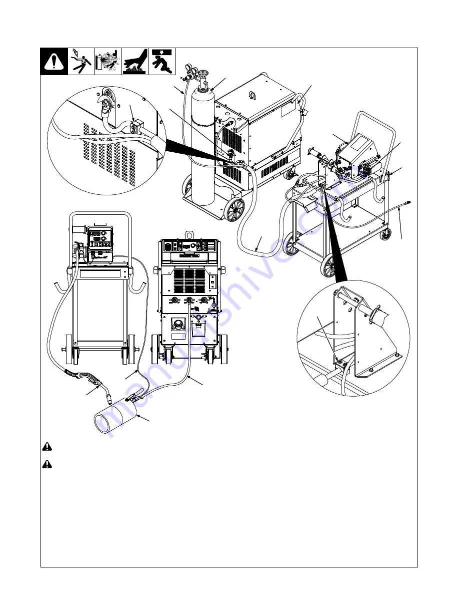
5-19. Typical Connection Diagram For MIG (GMAW) Equipment With Feeder
On Cart
!
Do not put feeder where welding
wire hits cylinder.
!
Do not move or operate equipment
when it could tip.
1
Welding Power Source
2
Wire Feeder
3
Feeder Cart
4
Composite Cable
5
MIG Connection
6
Positive (+) Weld Cable
7
Gas Hose
8
Gas Cylinder
Locate end of composite cable where gas
hose extends out of sleeve approximately
50 inches (1270 mm). This end of the
composite cable connects to the power
source. Connect 14-pin plug to rear of
power source, and connect 14-socket plug
to rear of wire feeder. Connect one end of
weld cable to weld terminal on rear of power
source and secure cable in clamp block on
rear panel. Connect remaining end of weld
cable to wire feeder drive housing and
secure cable in clamp block on feeder
base. Connect one end of gas hose to
regulator/flowmeter on gas cylinder and
connect remaining end of gas hose to gas
solenoid connector on rear of feeder or
Y-hose for dual wire feeder.
9
Work (
−
) Weld Cable (2/0 minimum)
.
Attach volt sense lead to work clamp
and attach work clamp as close to arc
as possible.
10 Volt Sense Cable
11 Workpiece
12 Welding Gun
13 Strain Relief Clamp
805 317-B
6
10
7
1
4
2
5
8
3
10
11
9
12
13
13
Содержание PipeWorx 400
Страница 14: ...OM 236 891 Page 10...
Страница 90: ...OM 236 891 Page 86 SECTION 8 ELECTRICAL DIAGRAMS Figure 6 1 Circuit Diagram For Welding Power Source...
Страница 91: ...OM 236 891 Page 87 254 310 B...
Страница 92: ...OM 236 891 Page 88 Figure 6 2 Circuit Diagram For Single Or Dual Wire Feeder...
Страница 93: ...OM 236 891 Page 89 236 220 E...
Страница 94: ...OM 236 891 Page 90 Figure 6 3 Circuit Diagram For Cooler 238 662 B...
Страница 95: ...OM 236 891 Page 91 Figure 6 4 Flow Diagram For Cooler Pump Filter Radiator Flow Indicator Tank Torch...


