


OM-275857 Page 25
�
Complete Parts List is available at www.MillerWelds.com
18
Output
+10 volts DC
With respect to pin 11 for use with an external potentiometer to vary the signal
into pin 17 (Pin C of 14 pin).
19
Input
High Frequency Arc Start
Disable
Disables the arc starter from being activated when connected to pin 8.
23
Output
Final Slope Sequence
Indication
Paired with Pin 24. Pin is closed to pin 24 when in Final Slope. Electrical
specifications: Open collector transistor maximum values 27 volts DC peak @
75mA. See Section 5-5 .
24
Output
Final Slope Sequence Indi-
cation Reference
Paired with pin 23. Connect to user’s external voltage supply common. See
Section 5-5 .
All other pins not used.
B. Welder Controlled Automation Mode (Pin 20 Connected To Pin 8) Automation 1
Use this mode when only the basic functions of the automation board are required, or if the welder needs to control the initial and final weld
timers. These functions include Start/Stop, Valid Arc Indication, Gas Control, High Frequency Arc Start Disable, Remote Memory Select, and
Emergency weld stop. The welding power source functions as a standard unit. Automation 2 mode should be used when an externally controlled
pulse waveform is needed, or if the welder’s amperage is affected by noise injected into the cabling between the remote equipment and the
welder.
A complete Parts List is available at www.MillerWelds.com
A. User Controlled Automation Mode (Pin 25 Connected To Pin 8) Automation 2
804746-B / 21816-A
1
4
9
15
21
26
28
25
20
14
8
3
2
7
6
5
13
12
11
10
19
18
17
16
24 23
22
27
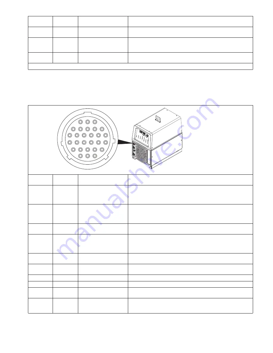
2-5.
Remote Memory Select Inputs (For 28-Pin Receptacle If Present)
1
4
9
15
21
26
28
25
20
14
8
3
Pin
Signal
Direction
Description
Pin Information For 28–Pin Receptacle RC28
1
Input
Start/Stop
Maintained connection to pin 8 starts the weld cycle. Opening connection
stops weld cycle. For momentary closure operation, set unit to 2T. A momen-
tary closure greater than 100 ms, but less than 3/4 of a second starts and
stops weld output.
2
Input
Emergency Weld Stop
Used to remotely stop the weld outside the normal welding cycle (i.e. light cur-
tains or external E-Stop). Connection to pin 8 must be maintained at all times.
If the connection is broken, output stops, Postflow begins, and will be dis-
played on the meters.
3
Input
Gas Control
This input is used to control the gas flow outside the settings of the preflow
and/or postflow set on the machine. Connection to pin 8 turns on gas.
4
Output
Valid Arc Indication
Paired with Pin 9. This output is used to signal external fixtures that the ma-
chine has detected a valid arc. Pin is closed to pin 9 when the output is on
and there is less than 65 load volts. Electrical specifications: Open collector
transistor maximum values 27 volts DC peak @ 75mA. See Section 5-5 .
5
Output
Scaled Actual Welding
Voltage
+1 volt DC per 10 volts of output w/reference to pin 11.
6
Output
Scaled Actual Welding
Amperage
+1 volt DC per 100 amperes of output w/reference to pin 11.
7
Output
+15 Volts DC
With respect to pin 11 (Pin A of 14 pin).
8
Output
Reference Pin
This pin is the signal reference for pins 1, 2, 3, 10, 15, 16.
9
Output
Valid Arc Indication
Reference
Paired with Pin 4. Connect to user’s external voltage supply common. See
Section 5-5.
10
Input
Memory Select
Used to select between memory numbers. Used in conjunction with pins 15
and 16. See Section 5-7.
Содержание Dynasty 400
Страница 77: ...OM 275857 Page 67 SECTION 12 ELECTRICAL DIAGRAMS 275852 H Figure 12 1 Dynasty 400 Circuit Diagram Page 1 of 2...
Страница 78: ...OM 275857 Page 68 275852 H Figure 12 2 Dynasty 400 Circuit Diagram Page 2 of 2...
Страница 80: ...OM 275857 Page 70 Figure 12 4 Maxstar 400 Circuit Diagram Page 2 of 2...
Страница 81: ...OM 275857 Page 71 275854 G Figure 12 5 Dynasty 800 Circuit Diagram Page 1 of 2...
Страница 82: ...OM 275857 Page 72 275854 G Figure 12 6 Dynasty 800 Circuit Diagram Page 2 of 2...
Страница 83: ...OM 275857 Page 73 Figure 12 7 Maxstar 800 Circuit Diagram Page 1 of 2...


