


OM-275857 Page 80
15-2. Pulser Control
OM-275857 Page 18
5-2.
Pulser Control
1
3
2
Peak Amp
Bkg Amp
PPS
1
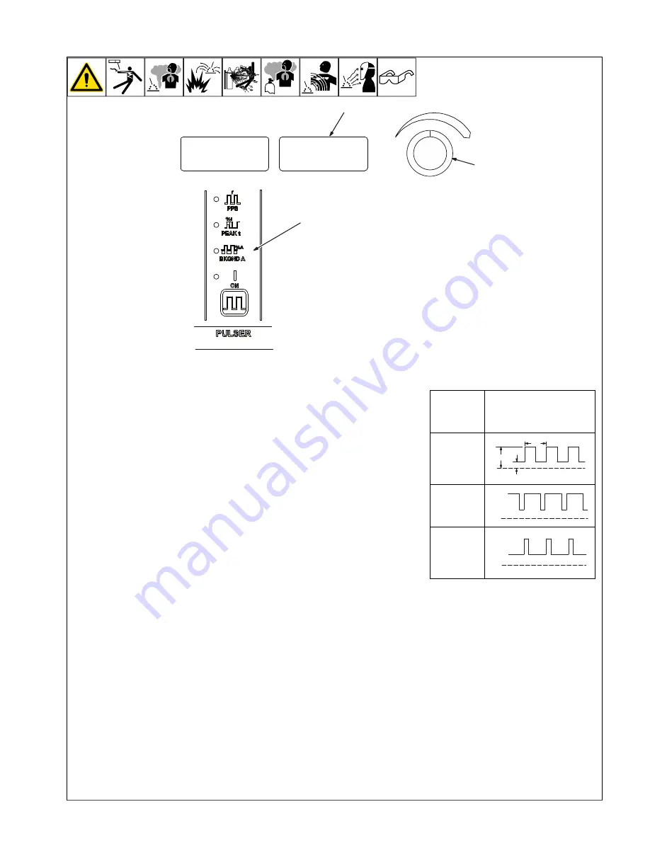
Pulser Control
Pulsing is available while using the TIG
process. Controls can be adjusted while
welding.
Press switch pad to enable pulser.
ON
- When lit, this LED indicates the pulser
is on.
Press switch pad until desired parameter
LED is lit.
To turn Pulser off, press and release switch
pad until the On LED turns off.
2
Encoder Control (Set Value)
3
Ammeter (Displays Value)
PPS
- Pulse frequency or pulses per sec-
ond, is the number of pulse cycles per sec-
ond. Pulse frequency helps reduce heat
input, part warpage, and helps weld bead
cosmetics. The higher the PPS setting, the
smoother the ripple effect, the narrower the
weld bead, and the more cooling you get. By
setting PPS on the lower end, the pulse is
slower, and the weld bead wider. This slow
pulsing helps agitate the weld puddle to help
release gas trapped in the weldment, and
help reduce porosity (very useful in alumi-
num welding). Some beginners use a slower
pulse rate (2-4 pps) to help them with their
timing on adding filler material. An experi-
enced welder may have the PPS setting
much higher, depending on their personal
preferences, and on what they are trying to
accomplish.
PEAK t
- (PEAK t) is the percentage of time
in each cycle, spent at peak amperage
(main amperage). Peak amperage is set
with the Amperage control (see Operation
section). If one pulse per second is being
used, and peak time is set at 50%, one-half
second is spent at peak amperage, and the
other 50%, or one-half second, is spent at
the background amperage. Increasing peak
time increases time spent at peak amper-
age, which increases heat input into the
part. A good starting point for peak time is
about 50-60%. To find a good ratio, you will
have to experiment a bit, but the idea is to
decrease heat input into the part, and in-
crease the cosmetics of the weld.
BKGND A
- (Background amps) is set as a
percentage of the peak amps setting. If peak
amps is set at 200, and background amps at
50%, your background amps is 100 amps
when the machine pulses on the back-
ground side of the cycle. The lower back-
ground amperage helps reduce heat input.
Increasing or decreasing background amps
increases or decreases the overall average
amperage, which helps determine how fluid
your puddle is on the background side of the
pulse cycle. Overall, you want your puddle
to shrink to about one-half the size, but still
remain fluid. To start with, set background
amps at about 20-30% for stainless/carbon
steel, or at about 35-50% for aluminum
alloys.
Table shows effect changing the Peak Time
control has on the pulsed output waveform.
Percent
(%) Peak
Time Con-
trol Setting
Pulsed Output
Waveforms
Peak 50%/
Background
50%
Balanced
50%
OM-275857 Page 18
5-2.
Pulser Control
1
3
2
Peak Amp
Bkg Amp
PPS
80%
More Time
At Peak
Amperage
OM-275857 Page 18
5-2.
Pulser Control
1
3
2
Peak Amp
Bkg Amp
PPS
20%
More Time
At Back-
ground
Amperage
OM-275857 Page 18
5-2.
Pulser Control
1
3
2
Peak Amp
Bkg Amp
PPS
Application:
Pulsing refers to the alternating raising and
lowering of the weld output at a specific rate.
The raised portions of the weld output are
controlled in width, height, and frequency,
forming pulses of weld output. These pulses
and the lower amperage level between them
(called the background amperage) alter-
nately heat and cool the molten weld puddle.
The combined effect gives the operator bet-
ter control of penetration, bead width,
crowning, undercutting, and heat input. Con-
trols can be adjusted while welding.
Pulsing can also be used for filler material
addition technique training.
�
Function is enabled when LED is lit.
Содержание Dynasty 400
Страница 77: ...OM 275857 Page 67 SECTION 12 ELECTRICAL DIAGRAMS 275852 H Figure 12 1 Dynasty 400 Circuit Diagram Page 1 of 2...
Страница 78: ...OM 275857 Page 68 275852 H Figure 12 2 Dynasty 400 Circuit Diagram Page 2 of 2...
Страница 80: ...OM 275857 Page 70 Figure 12 4 Maxstar 400 Circuit Diagram Page 2 of 2...
Страница 81: ...OM 275857 Page 71 275854 G Figure 12 5 Dynasty 800 Circuit Diagram Page 1 of 2...
Страница 82: ...OM 275857 Page 72 275854 G Figure 12 6 Dynasty 800 Circuit Diagram Page 2 of 2...
Страница 83: ...OM 275857 Page 73 Figure 12 7 Maxstar 800 Circuit Diagram Page 1 of 2...


