OM-287348 Page 38
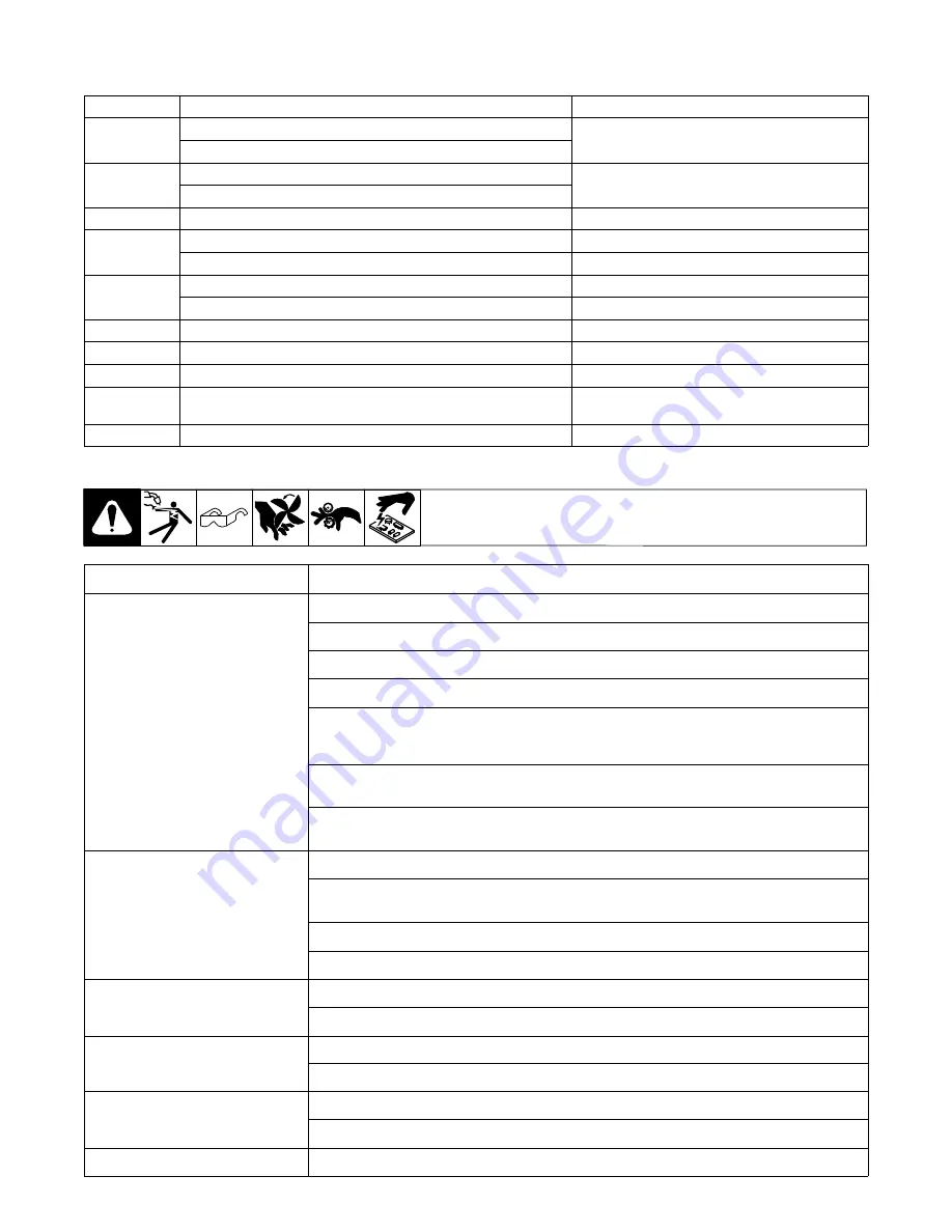
6-3. Error Code Troubleshooting Description And Table
Display Code
Fault
Description
004
Overtemperature - IGBT1 Primary Power Circuit
Overtemperature - IGBT2 Primary Power Circuit
005
Overtemperature - Secondary Rectifier
Overtemperature - Output Inductance
006
Overtemperature - Logic PCB (motor driver)
101/103
Temperature Sensor Failed - IGBT1 Primary Power Circuit
Temperature Sensor Failed - IGBT2 Primary Power Circuit
102/104
Temperature Sensor Failed - Secondary Rectifier
Temperature Sensor Failed - Output Inductance
105
Temperature Sensor Failed - Logic PCB (motor drive)
045
Trigger Protection
Torch trigger pressed: torch wiring issue.
131
Input Line Phase Alarm
Unit displays missing input line phase.
042
Motor Current Protection
A protection is activated when a high current is
absorbed by the motor.
040
Motor Encoder Alarm
6-4. Troubleshooting
Trouble
Remedy
No weld output; wire does not feed.
Be sure line disconnect switch is On (see Section 4-7).
Replace building line fuse or reset circuit breaker if open (see Section 4-7).
Secure gun trigger connections.
Check continuity of power switch S1 and replace if necessary.
Have Factory Authorized Service Agent check main transformer T1 for signs of winding failure. Check
continuity across windings and check for proper connections. Check secondary voltages. Replace T1
if necessary.
Have Factory Authorized Service Agent check continuity of thermostats TP4 and TP5. Replace TP4 and
TP5 if necessary.
Have Factory Authorized Service Agent check main control board PC1 and connections, and replace if
necessary.
No weld output; display boards front
panel PC1 and PC3 on.
Unit overheated, see Section 6-3.
Have Factory Authorized Service Agent check connections of J1 receptacle for damage if remote control
was connected.
Check remote control and replace if necessary
Have Factory Authorized Service Agent check front panel board PC1, and replace if necessary.
Maximum weld output, no current
control.
Check output LEM sensor HD1 connections and replace if necessary.
Have Factory Authorized Service Agent check front panel board PC1, and replace if necessary.
Fans do not work.
Check fans connections and supply voltage. Replace if necessary.
Have Factory Authorized Service Agent check front panel board PC1, and replace if necessary.
Low weld output with no control.
Check output LEM sensor HD1 connections and replace if necessary.
Have Factory Authorized Service Agent check front panel board PC1, and replace if necessary.
No wire feed.
Clear obstruction in gun contact tip or liner (see gun Owner’s Manual).
Содержание 059015051
Страница 4: ......
Страница 5: ......
Страница 57: ...Notes Securely connect work clamp to a clean area close to the weld joint Welding Tip...
Страница 58: ...Notes Work like a Pro Pros weld and cut safely Read the safety rules at the beginning of this manual...


