background image

36

Installation

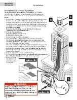
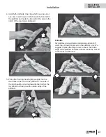
Re-install Support Legs (if removed)

With the fi rebox recessed behind the smoke curtain 
of the existing fi replace, raise the fi rebox and place 
the individual support legs under the fi rebox. Placing 
a temporary shim under the fi rebox, such as a 2” x 4”, 
may help while positioning the support legs. Tabs are 
provided on the support legs to help position them. 
Fasten the support legs at the points indicated by the 
arrows using the bolts provided (2 per side).

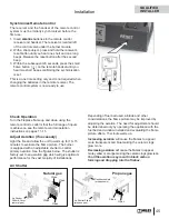
Level Firebox in Hearth

The backside of each support leg has a leveling bolt. If 
necessary, adjust the level of the fi rebox in the hearth.

Raise left hand side of firebox and slip 
LH support leg under.  Fasten with 
2 bolts as indicated.

Raise right side of firebox and slip 
RH support leg under. Fasten with 
2 bolts as indicated.

Leveling

bolt

Front View

Side View

Fret bracket

Leg

Leveling bolt

Back

Front

Leveling

bolt

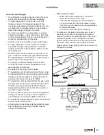
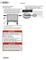
Re-install Burner Module

Note: If the circulating fan is to be installed it 
should be done at this point before installing the 
burner module. See instructions packaged with the 
fan for details of the fan installation.

Reinstall the burner module using the 10 screws 
removed previously. 

Note:

 The upper baffl  e may be removed to gain more 

room for the screwdriver to install the rear screws.

RF24JD-CL 

shown; 

same for CA

QUALIFIED 
INSTALLER

Содержание Valor Retrofire RF24JDN-CA

Страница 1: ...heating appliance It must not be used for any other purposes such as drying clothes etc This appliance is suitable for installation in a bedroom or bed sitting room INSTALLER Leave this manual with th...

Страница 2: ...13 Lighting Instructions 14 Servicing Maintenance 15 Servicing Your Fireplace 15 Annual Inspection 15 Cleaning Your Fireplace 16 Checking Pilot and Burner Flames 18 Replacing Batteries 19 Using Handse...

Страница 3: ...s Clothing or ammable material should not be placed on or near the appliance This unit must be used with a vent system as de scribed in this installation manual No other vent sys tem or components may...

Страница 4: ...sk individuals in the house Install an approved after market safety gate to keep toddlers young children and other at risk individuals a safe distance from the replace Keep the remote control handset...

Страница 5: ...ss window Do not let children touch the glass or any parts of your replace even after it is turned o as it is still hot Use the barrier screen provided with the trim or a gate to reduce the risk of se...

Страница 6: ...less manually lighting the pilot See full lighting instructions on page 14 of this manual Introduction Thank You For purchasing a Valor by Miles Industries Your new radiant gas heater is a technical a...

Страница 7: ...et use the wall switch if installed if the wall switch malfunctions and will not turn o the replace wait 6 hours and the replace will automatically go to pilot You can then access the controls inside...

Страница 8: ...h modes and settings 2 returns to set mode turns the burner and the pilot off Large flame button flames up sets hours temperature Small flame button flames down and off sets minutes temperature Curren...

Страница 9: ...RGH RXEOH FOLFN ODUJH DPH EXWWRQ ODPH DXWRPDWLFDOO JRHV WR KLJK UH ZLOO EH GLVSOD HG 0DQXDO 0RGH 0DQXDO ODPH HLJKW GMXVWPHQW SUHVV RZ DQG LJK LUH D WLPH 7HPSHUDWXUH 0RGH SSOLDQFH PXVW EH LQ VWDQGE PRG...

Страница 10: ...3UHVV 2 RU VLPSO ZDLW WR FRPSOHWH SURJUDPPLQJ 6 77 1 7 7 0 7 03 5 785 6 77 1 7 1 77 0 6 7 7 03 5 785 HIDXOW 6HWWLQJV VXQ HIDXOW 6HWWLQJV PRRQ 2 3UHVV ODUJH DPH EXWWRQ WR LQFUHDVH 1LJKWWLPH 6HWEDFN 7H...

Страница 11: ...OO WR 7 0 5 PRRQ ZKLOH WKH WLPH DVKHV 3UHVV ODUJH DPH EXWWRQ WR VHW WKH KRXU 3UHVV ODUJH DPH EXWWRQ WR VHW WKH KRXU 3UHVV VPDOO DPH EXWWRQ WR VHW WKH PLQXWHV 3UHVV VPDOO DPH EXWWRQ WR VHW WKH PLQXWHV...

Страница 12: ...H 7KH YDOYH ZLOO WXUQ WR SLORW DPH LI WKHUH LV QR FKDQJH LQ DPH KHLJKW IRU D KRXU SHULRG Q 7HPSHUDWXUH 7LPHU 0RGH LI WKH DPELHQW URRP WHPSHUDWXUH FKDQJHV WKH DPH KHLJKW ZLOO DGMXVW DXWRPDWLFDOO WR PDL...

Страница 13: ...Fret Kit required for all frets RA24CV Contemporary Vintage Iron Finish RA24AV Avant Garde Vintage Iron Finish RA24TB Traditional Black Finish 1225VFB Ventana Fret Black Conversion Kits RA24JDNK Conve...

Страница 14: ...QJ QHDU WKH RRr If you smell gas STOP Follow B in the safety information above on this label If you don t smell gas go to the next step 3 AUTOMA7 1 7 21 J RFDWH WKH SLORW J LQVLGH RI UHER DW HIW DQG V...

Страница 15: ...3 Inspect the operation of the ame safety system Pilot or Flame recti cation device 4 Inspect and ensure the lighting of the main burner occurs within 4 seconds of the main gas valve opening Visual in...

Страница 16: ...s have had good results from the products listed below We cannot however guarantee the results of these products Brasso Polish Plus by Kelkem Cook Top Clean Creme by Elco White O by Rutland Turtle Wax...

Страница 17: ...creen attached to the top of the rebox Push the bottom against the rebox to attach the magnets 6 Reinstall the bottom cover sliding its top ange into slots located at the bottom corners of the window...

Страница 18: ...ip of the thermocouple probe The main burner ame pattern will vary from appliance to appliance depending on the type of installation and climatic conditions The appliance area must always be kept clea...

Страница 19: ...ined to the rebox by a Velcro tab 1 Slide the bottom cover straight out from the slots located at the bottom corners of the window frame or unhook the fret CAUTION DO NOT USE a screwdriver or other me...

Страница 20: ...nce is shipped without a vent plate A vent plate is required for every installation Either RA24CL Co linear vent plate 3 x 3 or RA24CA Co axial vent plate 5 x 3 RA24CL OR RA24CA RF24JDN RF24JDP QUALIF...

Страница 21: ...having jurisdiction for installations at elevations above 4 500 feet 1 370 m Model JDN CA JDN CL JDP CA JDP CL Gas Natural Propane Altitude Ft 0 4 500 feet Input Maximum Btu h 20 000 18 000 Input Min...

Страница 22: ...ctioning solid fuel burning replace chimney Barrier Screen required included 2 3 ex liners see Venting Table for length alllowed WARNING HOT HEARTH FLOOR The hearth or oor in front of the replace may...

Страница 23: ...late with AutoFire supplied separately Co Linear Vent Plate 559SFK Flashing cut to required size and form drip edge on site 559CLT Terminal Fasten to Flashing with Sheet Metal Screws 3 locations 2 3 F...

Страница 24: ...lashing from 590FVK2 Existing unaltered functioning solid fuel burning replace chimney Barrier Screen required included 5 x 3 co axial using 590FVK2 ex vent kit WARNING HOT HEARTH FLOOR The hearth or...

Страница 25: ...nsert engine 40 max 8 min Approved co axial termination 5 x 3 to 6 5 8 x 4 adapter approved co axial 6 5 8 x 4 termination Co linear installation into existing F P RF24JD with RA24CA Co axial Vent Pla...

Страница 26: ...ombination of all the minimum dimensions shown possible may prove to be di cult installations 24 1 2 8 25 1 2 27 10 11 RA24TB Fret Black 1225VFB Ventana Fret Black RA24CV Fret Vintage Iron RA24AV Fret...

Страница 27: ...combination of all the minimum dimensions shown possible may prove to be di cult installations 24 1 2 8 25 1 2 27 10 11 RA24TB Fret Black 1225VFB Ventana Fret Black RA24CV Fret Vintage Iron RA24AV Fre...

Страница 28: ...end to allow for obstructions Venting Notes Where possible avoid splicing ex pipes If splices are required use a approved connector and seal joints with RTV high temp sealant Four feet horizontal is p...

Страница 29: ...eals o the top of the chimney space to avoid convective air loss The diagrams below show a typical terminal installation for an 8 diameter air cooled chimney system 559SFK Flashing cut to required siz...

Страница 30: ...and Co Axial Overhang should not extend beyond vent if within 48 of termination cap Horizontal overhang Vertical wall Min 24 unvented soffit Min 36 vented soffit Termination cap Min 18 Storm collar R...

Страница 31: ...me vertical adjustment of the cast iron fret should the fret need to sit on top of the curb otherwise the fret will need to be eliminated or adequate room provided behind the curb Gas Line Routing Pla...

Страница 32: ...e the RF24 rebox to be disassembled then reassembled inside the replace Plan your particular installation accordingly 1 Unhook barrier screen and window cover The screen is hooked to the window cover...

Страница 33: ...de the plate with liners attached onto the appliance in the cavity see next pages for more information In all case ensure the plate is hooked to the cleat at the back of the appliance Install Co Linea...

Страница 34: ...3 Apply RTV sealant to the collars on the vent slider and t the two liners ensuring that the exhaust liner is connected to the identi ed EXHAUST vent collar Secure with 4 tapping screws per liner or s...

Страница 35: ...rs are well secured and will not fall down the chimney 4 Apply a bead of sealant to top of chimney and seat ashing onto sealant 5 a Larger cavity opening Slide the appliance into the cavity b Smaller...

Страница 36: ...st the level of the rebox in the hearth Raise left hand side of firebox and slip LH support leg under Fasten with 2 bolts as indicated Raise right side of firebox and slip RH support leg under Fasten...

Страница 37: ...es in excess of psig 3 5 kPa The appliance must be isolated from the gas supply piping system by closing its individual manual shut o valve during any pressure testing of the gas supply piping system...

Страница 38: ...nstall Firebox Top Ba e if removed Installation Install Top Convection Ba e Position the rebox as far back as possible within the existing replace to allow ample space at front for the fret if used an...

Страница 39: ...op of the rebox into the guides on each side Slide the extension in or out to allow convection air to ow under the smoke curtain of the existing replace At the maximum the extension must cover the sma...

Страница 40: ...he sheet metal support Slide the log towards the left hand side until the notch in the log touches the right angled return edge of the pilot shield as indicated 2 Place the front left log on the burne...

Страница 41: ...gainst the front left log 5 Locate the top right log on the two pins on the right side of the rear log Ensure a tight t against the at area around the pins in the rear log 6 Place the lower end of the...

Страница 42: ...on top of the burner Logs 1 Identify the base log and place it in the cavity of the ceramic platform The protruding parts of the log in the front should rest against the lip of the sheet metal log sup...

Страница 43: ...ing its two pins into the two holes at the front of the platform The ends of the log should be oriented towards the front as the log should not hang over the inside edge of the platform Pebbles Six pe...

Страница 44: ...wer corner of the window reinstall it by sliding it between the glass and the frame as indicated x 4 WARNING Failure to install the window correctly can leak carbon monoxide a ect the performance of t...

Страница 45: ...ructions on pages 11 15 Adjust Aeration if necessary Light the re and allow the unit to warm up for 10 15 minutes to evaluate the ame picture The burner is equipped with an adjustable shutter to contr...

Страница 46: ...VHV VXFK DV GU LQJ FORWKHV HWF 7KLV DSSOLDQFH LV VXLWDEOH IRU LQVWDOODWLRQ LQ D EHGURRP RU EHG VLWWLQJ URRP 167 5 HDYH WKLV PDQXDO ZLWK WKH DSSOLDQFH 21680 5 5HWDLQ WKLV PDQXDO IRU IXWXUH UHIHUHQFH 3O...

Страница 47: ...ea of 3 4 inch 19 mm in front of the window is kept clear at all times Slide the top ange of the bottom cover into slots located at the bottom corners of the window frame Top Front Rear Top flange Bot...

Страница 48: ...e wall nd a convenient location and use the hardware provided with the kit See the diagram below for required hardware and con gurations Note that the holder can be installed at the base of a light sw...

Страница 49: ...49 Wiring Diagram Optional Wall Switch Kit 1265WSK or RBSWK Connector Red Yellow GV60 Wiring Diagram QUALIFIED INSTALLER...

Страница 50: ...GDSWHU WR 9 LQFO DVKLQJ OXPLQXP OH LEOH LQHU RU GLDPHWHU 127 SO OLQHU DSSURYHG WR 1 8 6 VXLWDEOH IRU YHQWLQJ JDV DSSOLDQFHV V PDQXIDFWXUHG E OH OH PDVWHU DQG RWKHUV R LQHDU 6HULHV R LDO 9 ODVKLQJV 5RR...

Страница 51: ...rranty does not cover damage to the unit due to i Improper installation operational or environmental conditions ii Inadequate ventilation in the area or competition for air from other household equipm...

Страница 52: ...Nut Pilot Pipe to Pilot Assembly 420K385 30 Electrode 4001856 31 Electrode Retaining Nut 4001855 32 Thermocouple 4000061 33 Pilot Shield 4000144 34 Pilot Gasket 4000139 Description Part No 35 Pilot M...

Страница 53: ...t MF28DWK 74 Rear Log 4005384 75 Base Log 4005383 76 RH Cross Log 4005381 77 Front Log 4005382 78 LH Cross Log 4005380 79 Small Beige Beach Pebble 3 4003087 80 Small Grey Beach Pebble 4003086 81 Brown...

Страница 54: ...78 76 77 82 81 80 79 MF28DWK MF28LSK Natural gas Propane gas 16 17 22 19 18 24 23 33 25 27 32 28 29 30 31 34 35 36 38 37 39 40 41 42 43 44 47 48 49 45 50 56 55 54 53 57 65 58 26 20 21 1 2 3 7 4 6 5 8...

Страница 55: ...ill be used for customer records only Online Warranty registration at www valor replaces com Cut out page ll information and mail to Miles Industries Ltd Fireplace Information Model Number RF24JDN CL...

Страница 56: ...Shut Thank you for choosing a Valor Product Postage needed Miles Industries Ltd 190 2255 Dollarton Highway North Vancouver BC V7H 3B1 Canada Fold here Online Warranty registration at www valor replace...

Отзывы: