


34
Installation
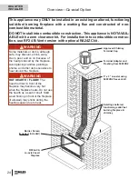
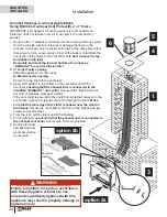
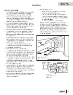
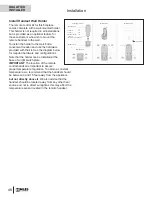
Connect Venting—Co-linear Applications
Using RA24CL Co-linear Vent Plate with 2 - 3” liners
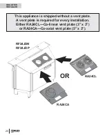
IMPORTANT: This appliance’s venting system is room sealed and
therefore, does not require room air to be used in the combustion
process.
1. Rough-in two 3” diameter vent liners into the existing chimney system
from the roof. Be careful not to tear or damage the liners in the
process. It may be easier to install both liners at the same time rather
than one at a time. Leave plenty of liner at the bottom to facilitate the
connection of the liners to the vent slider.
It is best to leave the top
termination until later.
Designate and mark the top and bottom of one liner as
“EXHAUST” to avoid confusion later.
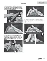
2. a) Larger cavity opening
Slide the appliance into the cavity.
b) Smaller cavity opening
Secure the two liners to the vent plate.
3. Apply RTV sealant to the collars on the vent slider and fi t the
two liners
ensuring that the
exhaust
liner is connected to the
identifi ed “EXHAUST” vent collar
. Secure with 4 tapping screws
per liner or stainless steel gear clamps.
If the vent slider is secured to the liners fi rst, slide the fi rebox onto the
vent slider in the cavity taking care not to damage the liners.
Make
sure that the rear edge of the slider is hooked over the cleat on
the fi rebox.
Secure the vent slider to the front of the fi rebox with two
screws removed earlier.
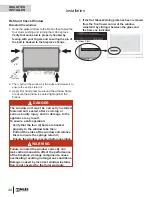
4. From the roof, pull the liners and fi t the fl ashing.
5. Fit the terminal cap
ensuring that the exhaust liner is connected to
the exhaust vent collar
. Secure with 8 screws provided.
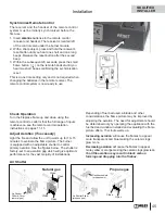
6. Seal the terminal
and fl ashing from
water penetration
as required.
1
3
4
5
option 2a
6
option 2b
Vent plate
cleat
WARNING
Failure to position the parts in accordance
with these diagrams or failure to use
only parts specifi cally approved with this
appliance may result in property damage or
personal injury.
WARNING
!
QUALIFIED
INSTALLER


