MAINTENANCE
TECHNICAL DOCUMENTATION
17
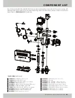
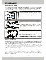
CLEANING THE INLET BALLOFIX VALVE
As part of the annual maintenance for the unit we recommend cleaning the integral basket filter in the
incoming ballofix valve to ensure it does not become blocked over time with dirt or debris from the incoming
water supply. To do this, the valve must be isolated and the cap on the left hand side of the valve should be
removed utilising a flat-head screwdriver. This will provide access to the filter which can be removed using a
pair of long nose pliers or similar tool. Once the filter is clean, the cap and filter must both be refitted and the
valve reopened.
STEPS 01 - 03
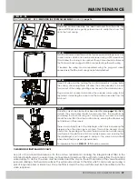
STEP 04:
STEP 05:
STEP 06:
STEP 07:
First follow
STEPS 01 - 03
for
REMOVING THE CONTROLS ASSEMBLY
detailed on
page 16
.
Once the controls assembly has been removed from the unit, the
pipework fittings can be gently pushed down to unclip them from their
slot in the front casing.
Turn the unit around and there will be four recessed retaining screws, one
in each corner, which can now be unscrewed using a PZ2 screwdriver.
This will allow the casing to be opened, though care should be taken as
the front and back casing will still be connected together with wiring.
If required, the wiring can be separated using the plug and socket
connectors so that the front casing can be fully detached.
Three PZ2 screws will be holding the manifold assembly in place inside
the casing. Unscrewing these will allow the entire assembly to be slid
forward out of the casing, granting easy access to the solenoid valves.
Plug and socket connectors will allow the solenoid valves wiring to be
separated, detaching the valves and the manifold assembly from the
main unit.
Once the valve to be cleaned has been identified (see
page 14
or
16
for
details) the valve head should be removed from the manifold by
unscrewing the four bolts using an 11mm spanner or socket. The valve
should then be lifted from the manifold body, ensuring the internals are
not disturbed in the process.
There is a small pilot hole in the diaphragm which aids in equalising the
pressure when the valve opens or closes. This must be cleared of any
obstruction. Depending on the valve, there may also be a small brass pin
and ferrule in the pilot hole which can safely be removed, ensuring that
the diaphragm is not damaged in doing so. The valve and manifold
base should then be given a general clean.
To reassemble the unit,
STEPS 01 - 07
should be reversed.
Содержание 3
Страница 2: ......
Страница 19: ...ISO 9001 Registered Quality Management 015 ...

