background image

MAINTENANCE

16

 TECHNICAL DOCUMENTATION

REMOVING THE CONTROLS ASSEMBLY

In the unlikely event of either a sensor or PCB failure, it may be necessary to replace the controls assembly. If 

this is the case then the unit must first be isolated mechanically and electrically, and then drained down by 

slackening the top inlet and system valve nuts, allowing any water in the internal pipework of the unit to drain 

out. Once this is done, the controls assembly may be removed by following the steps listed below. 

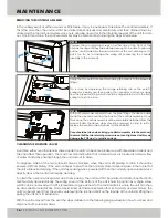
CLEANING THE SOLENOID VALVES

Over time either or both solenoid valves inside the unit can become blocked up with limescale or debris and 

this can affect their operation. The most common indication that a solenoid valve is blocked is a steady flow 

of water constantly passing through the unit and out to drain.

To diagnose which of the two solenoid valves is blocked, when the unit is still passing to drain it should be 

powered off completely. If the unit continues to pass then the normally closed solenoid valve in the top left of 

the unit will require cleaning. If the unit stops passing when powered off then the normally open solenoid valve 

directly above the tundish will require cleaning.

To clean the solenoid valve(s) and stop them passing, the unit must first be isolated and disconnected both 

mechanically and electrically. The wiring cover at the bottom of the unit is held in position by a single screw 

which can be removed with a PZ2 screwdriver to give access to the terminal block where the unit can then 

be disconnected electrically. Once fully isolated and disconnected both mechanically and electrically, the 

unit can be removed from the wall by unscrewing the slot-head bolt on the topside of the unit and lifting then 

pulling the unit from its backplate.

With the unit removed from the wall, the steps detailed on the following page will explain how to access and 

clean out both solenoid valves.

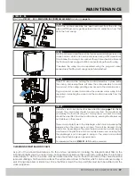
Unscrew the two retaining screws on either side of the front of the 

controls housing until they are extended enough to be able to grip and 

pull the control assembly forward and clear of the unit, ensuring not to 

pull it too far as to damage the wiring still connecting the controls 

assembly to the main unit.

Unclip the two push-fit connectors holding the sensors to the pipework 

fittings.

This is done by depressing the orange retaining clip on the push-fit 

connector inwards and then pulling the connector and sensor away 

from the pipework fitting, which should be clipped into a slot in the front 

casing to hold it in place.

With both sensors disconnected from the pipe fittings, the ribbon cable 

should then be removed from the back of the controls assembly. Once 

this is done, the controls assembly will be completely detached from the 

main unit and the above steps should be reversed in order to refit or 

replace the controls assembly back into the Mikrofill 3.

Care should be taken when fixing a controls assembly into the main unit 

to ensure that the two retaining screws are not over-tightened as this can 

damage the PCB and / or plastic casings.

STEP 01:

STEP 02:

STEP 03:

Содержание 3

Страница 1: ...P R E S S U R I S A T I O N U N I T MIKROFILL 3 PRESSURISATION UNIT TECHNICAL DOCUMENTATION ISSUE 12 15 Rev 01 I N S P I R E D E F F I C I E N C Y ...

Страница 2: ......

Страница 3: ...cal Diagram Electrical Data Keypad Functions System Data Up Power Down Service Mode Status Display Pressure Correct System Filling Filling Stopped due to Low Mains Water Pressure Frequent Use Service Mode Adjusting Settings Parameter Functions Fault Diagnosis Status Fault Conditions Status Fault Conditions continued Manual Override Component List Maintenance Removing the Controls Assembly Cleaning...

Страница 4: ...t Start Current Fuse Rating Maximum Load BMS Relays CONNECTION DETAILS Cold Water Inlet System Outlet Drain via Tundish Maximum Inlet Pressure Maximum Cold Fill Pressure Nominal Flow Rate Dry Weight 1806078 230 Volt 1 Amp 1 Amp 3 Amp 5 Amp 15mm Compression 15mm Compression BSP 5 Bar 4 7 Bar 14 l min at 2 Bar 5 kg ...

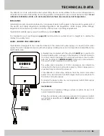
Страница 5: ...ly or a boosted cold water supply The unit is supplied complete with all necessary isolating valves and incorporates a basket filter in the inlet ballofix valve A flexible hose is supplied with the unit which MUST be connected to the inlet ballofix valve as shown in the diagram to the left Failure to do so may result in damage to the inlet pressure sensor due to water hammer resulting in a SENSOR ...

Страница 6: ... in excess of 1000L capacity please contact our technical department IMPORTANT NOTE DRAIN Following every fill procedure the unit will discharge a small amount of water establishing an air break For this the unit is supplied fitted with a BSP tundish which must be connected to a suitable drain Mikrofill Systems Ltd cannot accept responsibility for any consequential damage caused by failure to conn...

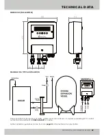
Страница 7: ...M OF A TYPICAL INSTALLATION Please note that for the purpose of clarity system valves are not shown For systems exceeding 90 C contact our technical department on 03452 60 60 20 for advice Further installation guidelines can be found on page 05 of this technical documentation ...

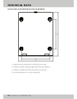
Страница 8: ...ONS FOR FIXING IN MILLIMETRES A maximum size of No 8 screws or M4 bolts are to be used A minimum of 25mm clearance either side of the unit is required A minimum of 250mm clearance above the unit is required The unit must be fitted on a sound solid surface 262 205 170 177 ...

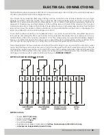
Страница 9: ...the unit will first need to be removed by unscrewing the PZ2 screw located on the underside Removing this cover will reveal a 12 way terminal block with each connection labelled 1 9 for the volt free relays see electrical installation diagram below Live Earth and Neutral The wiring can be passed through the cable glands on the underside of the unit through an opening in the front casing then conne...

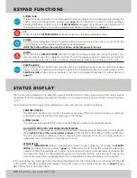
Страница 10: ...w the calibration code for the unit s pressure sensors by pressing and holding it down for 2 seconds The top line of numbers displayed will relate to the calibration of the unit SERVICE MODE This is a multi function button that when the unit is in operational mode is used to mute the audible alarm conditions Pressing and holding this button for approximately 8 seconds will put the unit into SERVIC...

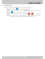
Страница 11: ...proximately 8 seconds The display will indicate that you are now in SERVICE MODE You can then release the button The button can now be used to scroll through the various settings To increase or decrease the value of a setting use the or buttons respectively After adjusting the settings the unit will save any changes made and return to its normal operating mode when no button is pressed for approxi...

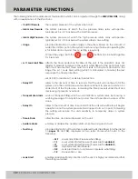
Страница 12: ...which is calculated in minutes the less responsive the flood protection set at 0 00 to disable Lvl 1 Leak Alert protection refers to the amount of time in seconds that the unit will continue to fill the system once the cold fill pressure has been reached to prevent overshoot or undershoot of the fill pressure increasing the time prevents undershoot and decreasing it prevents overshoot warns of fre...

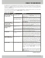
Страница 13: ... requires a dynamic mains pressure of 0 3 bar or more above its cold fill setting If the mains pressure usually satisfies this requirement then the cause of the mains pressure drop should be investigated The filter in the included mains inlet ballofix valve should be removed and cleaned to ensure flow into the unit is not being restricted see page 17 for details If the unit operates more than the ...

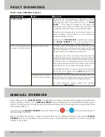
Страница 14: ...splay are fluctuating or the voltage is unstable when measured with a multimeter then there is likely an issue with the supply The unit can be powered from an alternative source or a power suppressor can be fitted to try and stabilise the incoming voltage to the unit In either case of SENSOR FAILURE the Mikrofill 3 can be put into MANUAL OVERRIDE to stop it from locking out any equipment on site d...

Страница 15: ...PRESSION CHECK VALVE Ø 15mm CHECK VALVE WITH FLOW REGULATOR Ø 15mm CONTROLS ASSEMBLY WITH SENSORS ISOLATION VALVE OUTLET 15mm COMPRESSION NORMALLY CLOSED SOLENOID VALVE NORMALLY OPEN SOLENOID VALVE O RING NITRILE 3mm I D x 3mm C S 11 12 13 14 15 16 17 18 19 MK3000034 MK3000017 MK3000028 MK3000029 MK3000019 MK3000020 MK3000021 MK3000024 MK3000025 O RING NITRILE 14 5mm I D x 3mm C S PCB POWER PIPE C...

Страница 16: ...PZ2 screwdriver to give access to the terminal block where the unit can then be disconnected electrically Once fully isolated and disconnected both mechanically and electrically the unit can be removed from the wall by unscrewing the slot head bolt on the topside of the unit and lifting then pulling the unit from its backplate With the unit removed from the wall the steps detailed on the following...

Страница 17: ...d be taken as the front and back casing will still be connected together with wiring If required the wiring can be separated using the plug and socket connectors so that the front casing can be fully detached Three PZ2 screws will be holding the manifold assembly in place inside the casing Unscrewing these will allow the entire assembly to be slid forward out of the casing granting easy access to ...

Страница 18: ...s Moat Redditch B98 9HL declare that the Mikrofill 3 pressurisation unit satisfies the essential requirements of the Electromagnetic Compatibility EMC Directive 2004 108 EC and the Low Voltage Directive LVD 2006 95 EC and is manufactured in accordance with the harmonised European standard BS EN 60730 1 2011 Signed by Steven Cherrington Technical Director United Kingdom 28th August 2015 ...

Страница 19: ...ISO 9001 Registered Quality Management 015 ...

Страница 20: ...North Moons Moat Redditch Worcestershire B98 9HL UK T 44 0 3452 60 60 20 F 44 0 3452 60 60 21 E info mikrofill com www mikrofill com Mikrofill Systems Ltd 11 Merse Road ...

Отзывы: