18
EasyARM v6
MikroElektronika
page
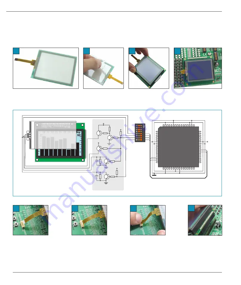
Figure 3 shows in detail how to connect a touch panel to the microcontroller. Bring the end of the flat cable close to
the CN38 connector (Figure A). Plug the cable into the connector (Figure B) and press it easily so as to fully fit the
connector (Figure C). Now, a GLCD can be plugged into the appropriate connector (Figure D).
NOTE:
LEDs and pull-up/pull-down resistors on port PORT0 should be off when the touch panel is in use.
Figure 1 shows how to place a touch panel over a GLCD display. Make sure that the flat cable is to the left of the GLCD,
as shown in Figure 1D.
13.0. Touch panel
A touch panel is a thin, self-adhesive, transparent, touch-sensitive panel. It is placed over a GLCD display. Its main function
is to register pressure at some specific display point and to forward its coordinates in the form of analog voltage to the
microcontroller. Switches 5, 6, 7 and 8 on the DIP switch SW3 are used to connect the microcontroller and touch panel.
Figure 13-2
: Touch panel connection schematic
D5
D4
D3
D2
D1
D0
E
R/
W
RS
LED-
Vo
LED+
VC
C
Ve
e
GN
D
RS
T
CS
2
D7
CS
1
D6
1
20
TOUCHPANEL
CONTROLLER
GLCD
Q4
BC856
Q2
BC846
VCC
VCC
VCC
VCC
Q
BC856
5
Q
BC846
3
R
1K
12
R
1 K
11
0
R
1 K
10
0
CN38
R
1 K
9
0
R
1K
8
R
K
16
100
R
1K
14
R
1 K
15
0
R
K
17
100
C14
100nF
C1
5
100nF
R
1 K
13
0
Q
BC846
6
SW3
P0.29
P0.30
P0.12
P0.13
BO TOM
T
LEFT
DRIVEA
DRIVEB
LEFT
LEFT
TOP
TOP
RIGHT
RIGHT
BOTTOM
BOTTOM
LPC2148
P1.27
P0.31
GND
P0.
0
P1.31
P0.
1
P0.
2
VCC3
P1.26
GND
P0.
3
P0.
4
P1.25
P0.
5
P0.
6
P0.
7
P1.24
VREF
XT
AL1
XT
AL2
P1.28
GNDA
P0.23
RESET
P1.29
P0.20
P0.19
P0.18
P1.30
VCC3
GND
VBA
T
P0.21
P1.20
P0.17
P0.16
P0.15
P1.21
VCC3
GND
P0.14
P1.22
P0.13
P0.12
P0.11
P1.23
P0.10
P0.9
P0.8
P0.22
RTXC1
P1.19
RTXC2
GND
VCCA
P1.18
P0.25
D+
D-
P1.17
P0.28
P0.29
P0.30
P1.16
VCC3
Figure 13-3
: Connecting touch panel
D
C
B
A
A
B
C
D
Figure 13-1
: Placing touch panel over a GLCD


